background image

Mode Change and Operation

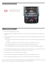
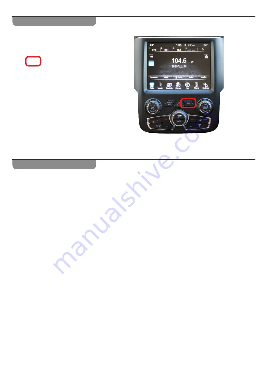
Long press BACK button while 

driving forward to activate

Fig. 7


y

Gain access to the back of the monitor.


y

Unplug the quad lock connector from the factory monitor and insert provided Plug and Play Quad Lock T 


Harness.


y

In the Plug and Play Harness, there are two yellow RCA connectors joined together. Disconnect these and do 
the following:-


h

Connect the female RCA from the vehicle side of the harness to the Male Video Output of VSW Video 
Switch


h

Connect the male RCA from the vehicle side of the harness to the VSW Video 1 Input


h

The Blue/White Trigger wire is not used for this installation and should be isolated.


h

Connect the Black wire of the VSW to ground along with the Black wire from the V2P-II Interface


y

Connect the White/Red Video 2 Trigger of the VSW to the Red Switched Power wire Output of the V2P-II 
Interface. When a video signal is present on the RCA this wire will output 12v.


y

Connect the Yellow 12v (+) of the V2P-II to ACC or Ignition.


y

Connect the RCA Video Output of the V2P-II to the Video 2 Input of the VSW Video Switch.


y

Connect the RCA Video cable from the caravan camera to the video female input of the V2P-II

To activate the front camera while driving forward simply long press the BACK Button on the radio for 2-3 seconds.
Please refer to the wiring diagram on the next page 

(Figure 6)

 for more information.

Installation Guide

Summary of Contents for 1296-1

Page 1: ... labels on the product including software versions and serial numbers must not be covered damaged or re moved This may void the warranty on the product Ensure that all left over accessories including remote controls and cables are given to the customer If replace ments are required in the future they will be charged Please ensure the installation of this product will not interfere with any factory...

Page 2: ...t 6 RCA MALE 7 RCA Sheild 8 CAN HI Radio Side Brown White 9 CAN HI Car Side Blue White 10 Ground Black PIN Description Colour 11 OUTPUT 1 Provides 12v ACC Out White Red 12 OUTPUT 2 when AUX is activated AVSW V1 Trigger Blue White 13 OUTPUT 3 when Front Camera is activated AVSW V2 Trigger Purple 14 TX INPUT UART control to SVS 6 RX White Brown 15 RCA Femal Normally Open 16 RCA Female Normally Close...

Page 3: ... is not used for this installation and should be isolated h h Connect the Black wire of theVSW to ground along with the Black wire from theV2P II Interface y y Connect the White Red Video 2 Trigger of the VSW to the Red Switched Power wire Output of the V2P II Interface When a video signal is present on the RCA this wire will output 12v y y Connect theYellow 12v of theV2P II to ACC or Ignition y y...

Page 4: ... unless using Plug PlayT Harness Input 1 Input 3 Output 1 VIM CIM Enable Input 2 Force Rear Cam Force Front Cam 12v REV OUT Output 2 12v FVC OUT Output 3 12v ACC OUT From OEM Harness Video Output Switched Power PLEASE NOTE Wire colours are subject to change without notice Please refer to PIN LOCATION and or Label for reference instead of colour Join wires Not required for this application Installa...

Reviews: