Advanced Instruments, Inc.
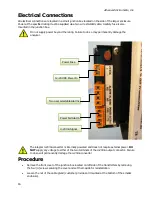
Gas Connections: Inlet and outlet vent gas lines require 1/8” diameter tubing preferably metal.
Power Connection: Locate a source of AC power to meet area classification and to plug in the charging
adapter.
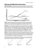
Zero Calibration: Required only for very low percentage range measurements, less than 5% of full
scale at the most sensitive range of the analyzer.
Span Calibration: Users are responsible for certified span gas cylinder, regulator and flow control valve.
The analyzer must be calibrated with a certified span gas and regular intervals, typically every 30 days of
operation.
Mounting the Analyzer
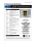
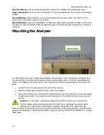
The GPR-2500A is housed in a Fiber Glass NEMA4X rated enclosure. This configuration is designed to be
mounted directly to any flat vertical surface, wall or bulkhead plate with four (4) of the appropriate size
screws. To facilitate servicing the interior of the transmitters, position it approximately 5 feet off ground
level.
•
Loosen the four mounting pads at the rear of the enclosure.
•
Select four appropriate mounting screws (customer supplied).
•
Secure the enclosure to a vertical surface approximately 5 feet from the floor or a level accessible
to service personnel. This requires the user to supply four (4) additional proper size screws and
anchors.
Caution: Do not remove or discard the gaskets from either the enclosure or junction box.
The transmitters design provides protection from RFI that is maintained by leaving specific
mating areas of the enclosure unpainted to maintain conductivity of the gasket, top and
bottom sections of the smaller enclosure housing the electronics. These unpainted areas are protected by
gaskets and contribute to maintaining the NEMA 4 rating as well as protection from RFI/EMI. Do not paint
these areas.
Mounting Pads
13


