20 Gear Drive, Plymouth Ind. Park, Terryville, CT 06786
Tel: (860) 585-1254 Fax: (860) 584-1973 http://www.amci.com
SMD23E2 and SMD24E2 User’s Manual
I
NSTALLING
THE
SMD23E2
OR
SMD24E2
87
1.4 Mounting (continued)
1.4.3 SMD23/4E2-M12P Mounting
The SMD23E2-M12P and SMD24E2-M12P units are water tight. Their IP67 rating makes them acceptable
for use in washdown environments and can be exposed to low pressure / low volume water sprays as well as
temporary immersions.
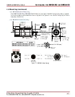
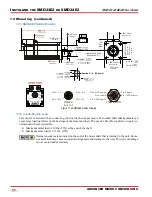
1.4.4 SMD23E2 Outline Drawing
Figure T1.1 SMD23E2 Outline Drawing
0.003"
(0.08)
A
A
Section S – S (3X Scale)
+ 0.000
– 0.013
)
(
2.25"
max.
(57 max.)
1.60"
Max.
(40.6)
1.520"
±0.005"
(38.61 ± 0.13)
0.81"
±0.04"
(20.6 ±1)
0.19"
±0.01"
(4.8 ±0.3)
0.06"
±0.01"
(1.5 ±0.3)
S
AMCI Motor
SMD23E2-130(E,A)-M12(S,P)
SMD23E2-240(E,A)-M12(S,P)
Length
3.93" (99.8)
4.73" (120.1)
2
.25"
ma
x
(5
7 m
a
x)
1
.856
"
±
0
.0
0
8
"
(4
7.
1
4
±
0
.2
)
4: 4.6
4: 0.18"
+ 0.5
– 0.0
)
(
0.001"
(0.03)
+ 0.000
– 0.013
)
(
S
1.856"
±0.008"
(47.14 ±0.2)
POWER & INPUTS
Pin 1: +Tx
Pin 2: +Rx
Pin 4: –Rx
Pin 3: –Tx
Pin 1: DCPower
MAIN
Pin
5: DCPower
AUX
Pin 2: Input 1
Pin
3: DC Common
Pin 4: Input 2
Optional Nitrile Shaft
Seal (Options “S”, “P”)
Port 2
Port 1
Power: 24 to 48 Vdc
Module
Status
Network
Status
Power & Inputs
ETHERNET
Ports 1 & 2


