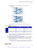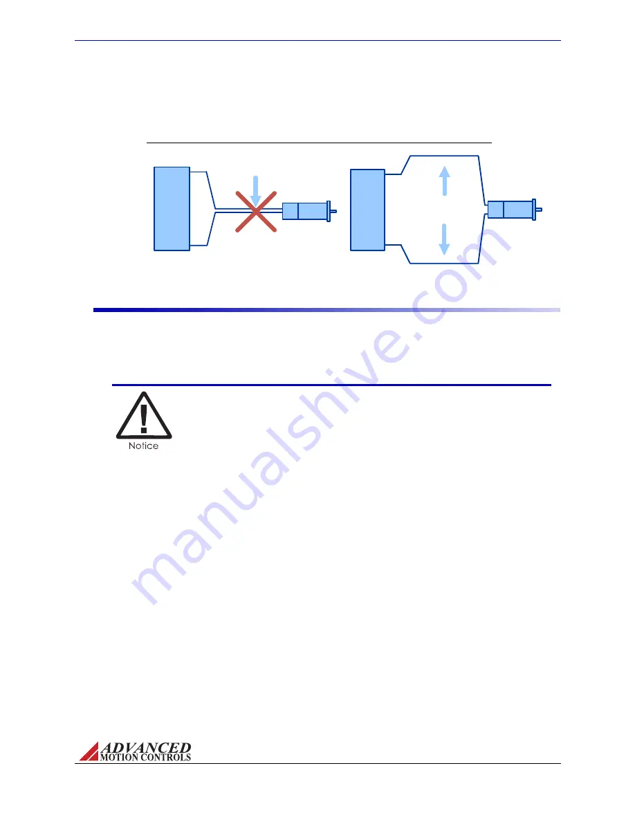
FIGURE 3.2
Feedback Wiring
Motor Feedback
Motor Power
Avoid running
feedback and power
wires together
Motor Feedback
Motor Power
Separate power and
feedback wires
where possible
Motor
AZ SERVO
DRIVE
Motor
AZ SERVO
DRIVE
MNALAZIN-02
21
Integration in the Servo System / Wiring
motor, try to find separate paths that maintain distance between the two. A rule of thumb for
the minimum distance between these wires is 10cm for every 10m of cable length.
Input Reference Wires
Use of a twisted, shielded pair for the input reference wires is recommended. Connect the
reference source "+" to "+REF IN", and the reference source "‐" (or common) to "‐REF IN".
Connect the shield to the mounting card or PCB interface chassis ground. The servo drive’s
reference input circuit will attenuate the common mode voltage between signal source and
drive power grounds.
In case of a single-ended reference signal, connect the command
signal to "+ REF IN" and connect the command return and "- REF IN" to
signal ground.
Long signal wires (10‐15 feet and up) can also be a source of noise when driven from a typical
OP‐AMP output. Due to the inductance and capacitance of the wire the OP‐AMP can oscillate. It
is always recommended to set a fixed voltage at the controller and then check the signal at the
drive with an oscilloscope to make sure that the signal is noise free.
Artisan Technology Group - Quality Instrumentation ... Guaranteed | (888) 88-SOURCE | www.artisantg.com


