MNALAZIN-02
25
Integration in the Servo System / Mounting
Soldering
Soldering an AZ board directly to a PCB provides added support against mechanical
shocks and vibration. It is recommended to solder AZ drives to a PCB following the industry
standard for Acceptability of Electronic Assemblies IPC‐A‐610D. Use solder with no‐clean flux.
AZ drives can be soldered by any of the following methods:
•
wave soldering
•
hand soldering
•
selective wave soldering
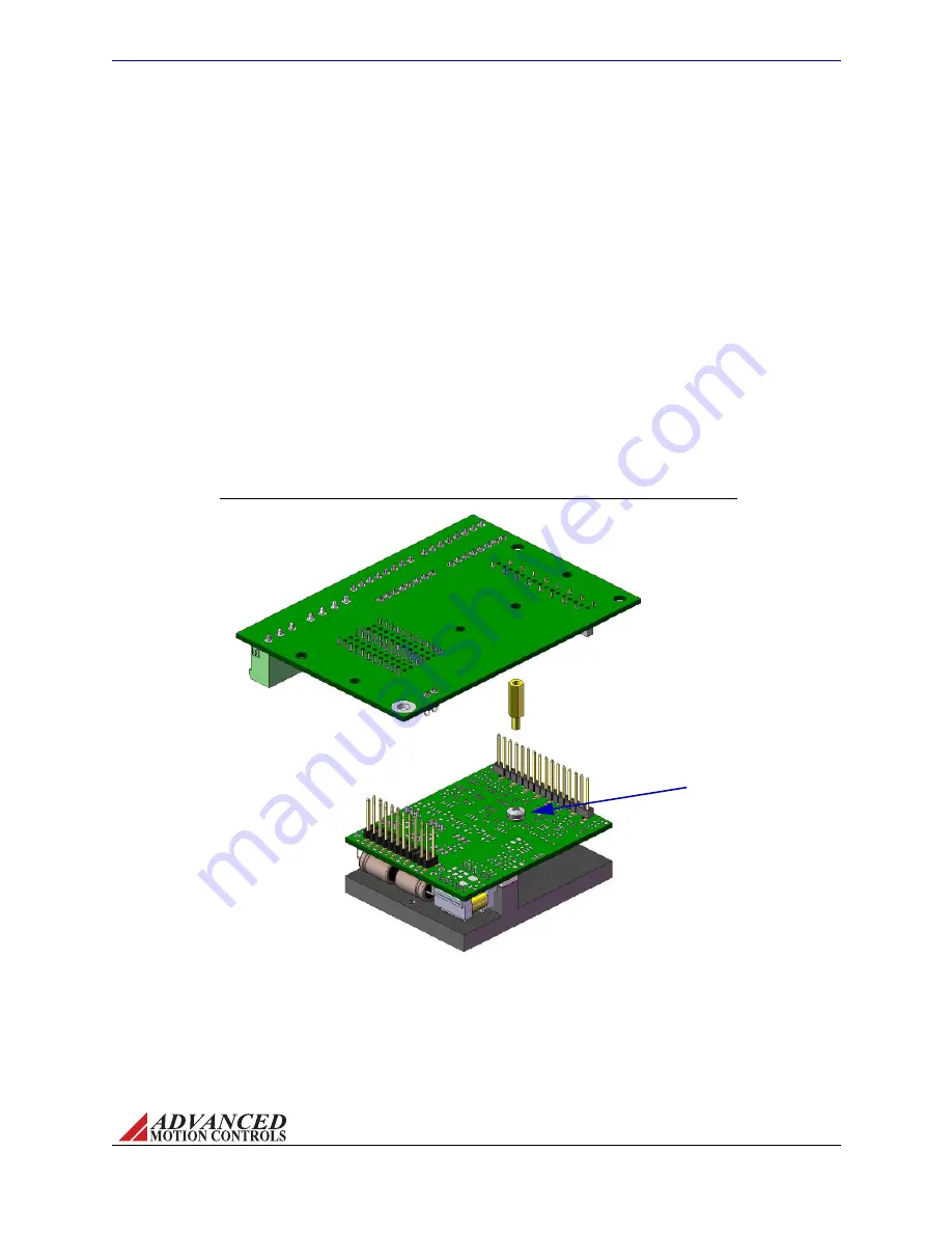
FIGURE 3.5
Remove drive mounting screw,
and replace with spacer*. Use
the removed drive mounting
screw to secure mounting card
to drive from the bottom of the
mounting card through the
spacer after drive has been
inserted in mounting card
socket connectors.
*Spacer not included with AZ drive or
mounting card. Spacer shown is
standard 3/16" hex 4/40 thread,
male/female, 7/16" length.
Drive Mounting Screw
AZ20 Screw Mount Diagram
To clean the PCB and drive after soldering, it is recommended to gently apply isopropyl alcohol
or a cleaning agent with a soft‐bristled brush. Use care not to apply downward pressure, but
rather lightly brush the PCB and drive. Do not immerse the drive in a cleaning agent.
Screw Mounting
For added stability and support, AZ drives can be mounted with screws in
tandem with one of the options above.
Figure 3.5
shows how an AZ20 drive can be mounted to
the MC1XAZ01 mounting card using a spacer. See
“Physical Dimensions” on page 39
and/or
the specific drive’s datasheet for exact screw locations and dimensions.
Artisan Technology Group - Quality Instrumentation ... Guaranteed | (888) 88-SOURCE | www.artisantg.com


