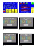
System settings provide access to the COMM parameters, I/O test and Memory Card information.
COMM parameters are set at the factory as follows:
SIG LEVEL: RS232C
CONNECT: 1:1
PC Stat: No: 1
Baud Rate: 19,200
Data: 8
Stop Bit: 1
Parity: ODD
I/O test provides for TOUCH/CONTACT SWITCH tests. Each button can be tested to ensure proper
operation of the screen. Press the
right corner
of screen to return to the main menu.
From the main menu, press System / Mode to return to normal operation.
3.8 Touch Screen Program / Color Scheme
The touch screen displays 16 true colors and 16 shaded colors to provide a vivid display. A particular
color scheme is used to assist the operator to locate functions:
Blue
is the background color used for text information. No “buttons” or functions are blue.
Green
is the color used for “buttons” that change settings. Pop-up windows may be displayed or a
function is turned on/off for instance.
Red
indicates that a function is off or stopped. Pressing a red button may turn a function on for instance.
Yellow
is the color used for menu buttons. A menu button displays another screen and allows for
movement throughout the entire program.
With an understanding of this basic color scheme, the operator will quickly setup the system or make
minor adjustments during operation.
The touch screen program
is a “user-friendly” menu-driven setup and operation program. Moving
through the system is accomplished by touching the area of the screen that describes the desired
operation.
3.9 Calibrating Screen
When the US-4000 is turned on, a Calibration Screen is displayed on the touch screen for approximately
30 seconds momentarily while the scale program initiates and automatically calibrates the load cell. See
Fig. 3-1.
3.10 Pass Code Function
Advanced Poly-Packaging, Inc. (APPI) has included a pass code function in all touch screen
equipment to prevent operators from changing settings. (Available on program versions 4.08
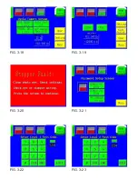
and higher). See Fig. 3-21 through 3-23.
There are two pass code levels described as follows:
1. Level 1: This is the highest level pass code which prevents operators from accessing the
Technical Assistance functions of the machine. Additionally, the pass codes are maintained in
this area.
2. Level 2: This level pass code, when the pass code function is enabled, prevents the operator
from accessing settings screens that affect the operation of the equipment.
Pass codes prevent unauthorized individuals from tampering with settings. When equipment is
shipped, APPI uses the following codes which can be changed by the customer at any time:
Summary of Contents for US-4000
Page 2: ...This page intentionally left blank ...
Page 6: ...This page intentionally left blank ...
Page 8: ...Chapter 5 Maintenance Trouble Shooting 5 1 Troubleshooting Checklist Chapter 6 Parts Drawings ...
Page 12: ...This page intentionally left blank ...
Page 15: ......
Page 16: ...This page intentionally left blank ...
Page 20: ...FIG 3 1 FIG 3 2 FIG 3 3 FIG 3 4 FIG 3 4A FIG 3 5 ...
Page 21: ...FIG 3 6 FIG 3 7 FIG 3 8 FIG 3 9 FIG 3 10 FIG 3 11 ...
Page 27: ...FIG 3 12 FIG 3 13 FIG 3 14 FIG 3 15 FIG 3 16 FIG 3 17 ...
Page 28: ...FIG 3 18 FIG 3 19 FIG 3 20 FIG 3 21 FIG 3 22 FIG 3 23 ...
Page 30: ...This page intentionally left blank ...
Page 33: ......
Page 34: ......
Page 35: ......
Page 36: ......
Page 37: ...Chapter 5 Trouble shooting Troubleshooting Checklist ...
Page 39: ...Chapter 6 Replacement Parts Components Lists with Drawings ...
Page 41: ......
Page 43: ......
Page 45: ......
Page 47: ......
Page 49: ......
Page 51: ......
Page 53: ......
Page 54: ......


