Page 12
ES/ESH-LT209_10152019
Single Stage Unitary Range
INSTALLATION
Tube Installation
•
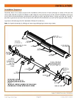
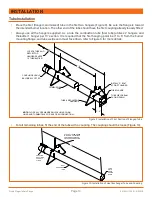
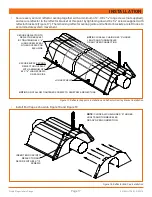
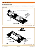
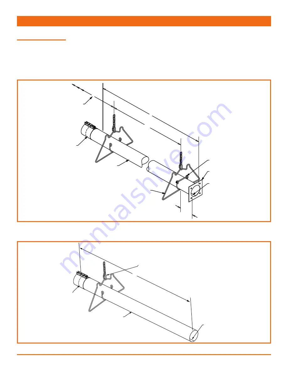
Place the first (flanged, aluminized) tube in the first two hangers (Figure 9). Be sure the flange is toward
the intended burner location. The other end of the tube should have the first coupling already loosely fitted.
•
Always use all the hangers supplied. As a rule the combustion tube (first tube) utilizes 2 hangers and
thereafter 1 hanger per 10’ section. It is required that the first hanging point be 3” to 6" from the burner
mounting flange, and tube weld seam must face down, refer to Figure 9 for more details.
Figure 9: Installation of First Section of Flanged Tube
COUPLING SHOULD
BE LOOSELY FITTED
10'
8' - 9'
10'
3" - 6"
COMBUSTION
TUBE
TUBE & REFLECTOR
HANGERS
LOCATE TUBE AND
REFLECTOR
HANGERS EVERY
10' THEREAFTER.
NOTE:
CLOSE ALL OPEN-ENDED QUICK LINKS, CHAIN
LINKS,AND TURNBUCKLES OR ANY OPEN CONNECTION.
INSTALL "J" BOLT
AT FIRST HANGER
TUBE FLANGE
TUBE WELD SEAM
FACING DOWN
•
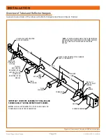
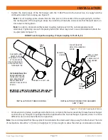
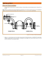
For all remaining tubes, fit the end of the tube with a coupling. The coupling should be loose (Figure 10).
Figure 10: Installation of Heat Exchanger Tube and Coupling
10'
COUPLING
SHOULD BE
LOOSELY
FITTED
HEAT
EXCHANGER
TUBE
CLOSE ALL OPEN ENDED
"S" HOOKS, CHAIN LINKS,
AND TURNBUCKLES OR
ANY OPEN CONNECTION.
TUBE
WELD
SEAM
FACING
DOWN
Summary of Contents for ES/ESH Series
Page 2: ......


