Page 17
Single Stage Unitary Range
ES/ESH-LT209_10152019
INSTALLATION
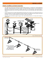
•
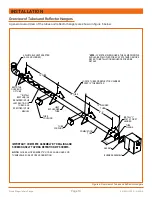
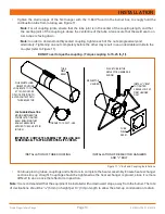
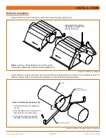
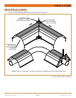
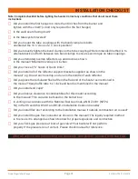
Secure every second reflector overlap together with a minimum of 2 - #8 x 3/8” long screws (not supplied),
and secure reflector to the reflector bracket at this point by tightening down #8 x 1¼” screws supplied with
reflector brackets (Figure 17). The remaining reflector overlap joints and reflector brackets are left loose to
accommodate system movement.
Figure 17: Reflector Supports Installation and Reflector Overlay Bracket Installation
LOOSE SCREWS
SECURE REFLECTOR TO
REFLECTOR BRACKET
BY TIGHTENING #8 X
¹/
4
"
LONG SCREW EVERY
OTHER OVERLAP ON
EACH SIDE
SECURE EVERY SECOND
REFLECTOR OVERLAP
WITH A MINIMUM OF 2
#8 X
³/
8
"
LONG SCREWS
ON EACH SIDE
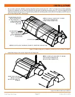
NOTE:
CLOSE ALL CHAIN LINKS “S” HOOKS,
J BOLTS AND TURNBUCKLES
OR ANY OPEN CONNECTION
NOTE:
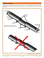
DO NOT ALLOW TIGHTENED SCREWS TO PENETRATE REFLECTORS
•
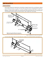
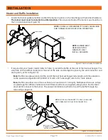
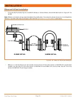
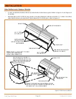
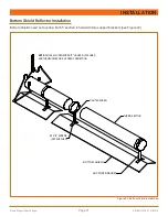
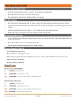
Install End Cap as shown in Figure 18 and Figure 19
Figure 18: Reflector End Cap Installation
REFLECTOR ENDCAP AND SUPPORT INSTALLATION
NOTE:
CLOSE ALL CHAIN LINKS “S” HOOKS,
J BOLTS AND TURNBUCKLES
OR ANY OPEN CONNECTION
INSERT END CAP INTO
REFLECTOR AND
SECURE WITH #8 X
³/
8
"
SCREWS
Summary of Contents for ES/ESH Series
Page 2: ......


