background image

Page 28 

ES/ESH-LT209_10152019

Single Stage Unitary Range

ELECTRICAL WIRING

Wiring Diagrams

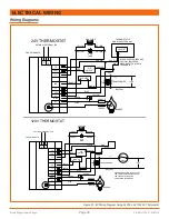
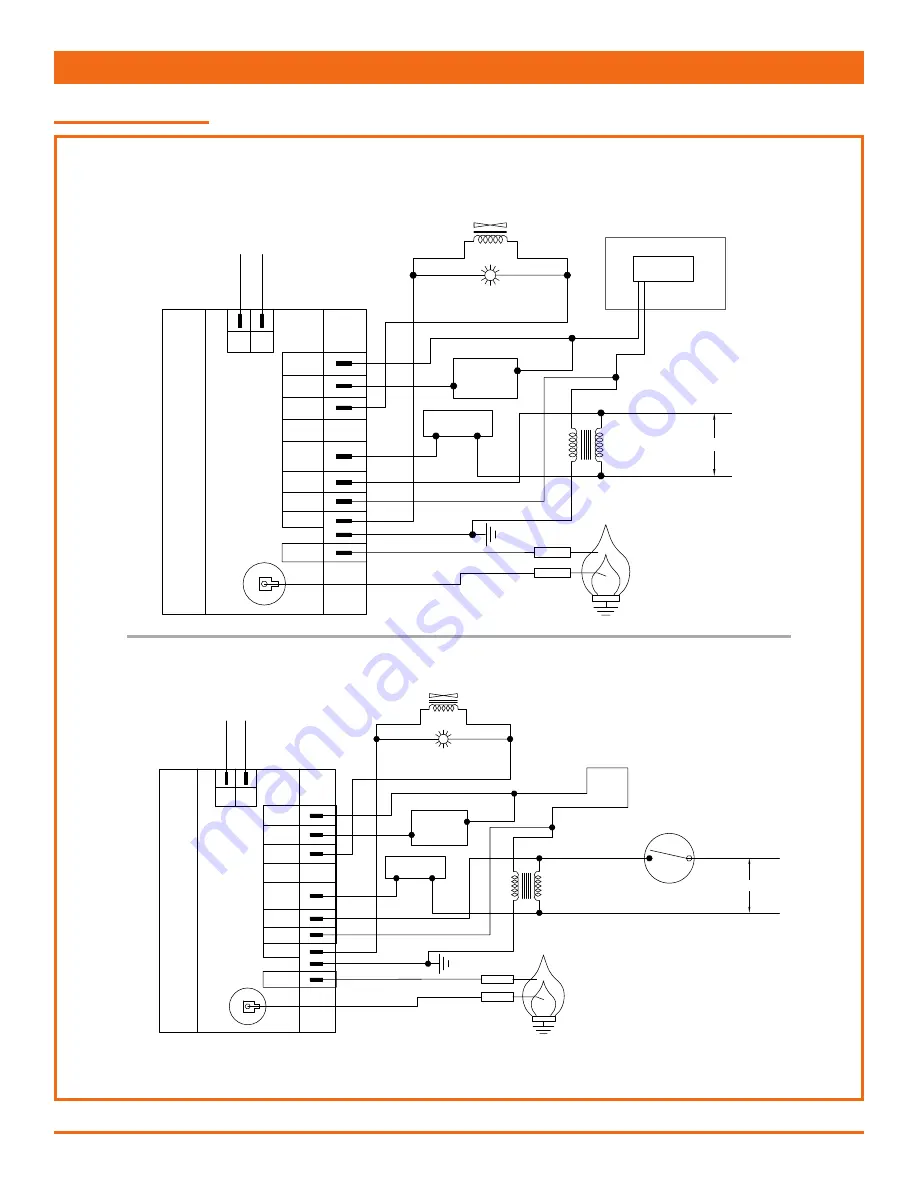
Figure 30: ES Wiring Diagram Using 24VAC and 120VAC Thermostat

OPTIONAL EXTERNAL LED

CNE DSI MODULE

GAS VALVE

YELLOW

YELLOW

YELLOW

BROWN

BROWN

PURPLE

PURPLE

BLUE

RED

RED

BLACK

BLACK

BLACK

PINK

GREEN

BLUE

BLUE

RUN

LAMP

AIR

SWITCH

BLOWER

SENSOR

IGNITER

BURNER

NEUTRAL

24V

TRANSFORMER

L1

120V

TH

PSW

V1

IND

L1

24V

V2

GND

S1

HV

D-

D+

T'STAT*

WHEN CONNECTION 120 VAC STAT,

THE TWO BLUE WIRES USED FOR

THE 24VAC STAT MUST BE

CONNECTED INTERNALLY.

120V THERMOSTAT

OPTIONAL EXTERNAL LED

CNE DSI MODULE

GAS VALVE

YELLOW

YELLOW

YELLOW

BROWN

BROWN

PURPLE

PURPLE

PURPLE

RED

RED

ORANGE

BLACK

BLACK

PINK

GREEN

BLUE

BLUE

RUN

LAMP

AIR

SWITCH

BLOWER

SENSOR

IGNITER

BURNER

NEUTRAL

24V

TRANSFORMER

L1

120V

TH

PSW

V1

IND

L1

24V

V2

GND

S1

HV

D-

D+

THERMOSTAT IS

MOUNTED EXTERNALLY

BLUE & PURPLE WIRES ARE

FACTORY JUMPERED,

DISCONNECT TO WIRE IN

THERMOSTAT

24V STAT

R

W

24V THERMOSTAT

Summary of Contents for ES/ESH Series

Page 1: ...Installation Operation and Service Instructions ES ESH RANGE SINGLE STAGE UNITARY INFRARED HEATERS ...

Page 2: ......

Page 3: ...cated in hazardous atmospheres containing flammable vapors or combustible dusts Signs should be provided in storage areas specifying maximum safe stacking height CAUTION MECHANCIAL HAZARD This equipment expands and contracts with each operating cycle The gas connection suspension hardware and the installation itself must safely allow this movement Failure to do so could result in serious fire or e...

Page 4: ...tom Shields 20 Bottom Shield Reflector Installation 21 Decorative Grille Optional 22 VENTING AND COMBUSTION AIR DUCTING 23 General Requirements 23 Un Vented Operation 23 Horizontal Venting 24 Vertical Venting 25 Common Vertical Venting 25 Combustion Air Supply Optional 26 Outdoor Installation ESH Models Only 26 GAS PIPING 27 General Requirements 27 ELECTRICAL WIRING 27 General Requirements 27 Wiri...

Page 5: ...A 88A or Standard for Repair Garages NFPA 88B in the US and CSA B149 1 and B149 2 Installation Codes in Canada Parking Structures Technical requirements are outlined in ANSI NFPA 88B USA Gas Supply Lines Gas supply pipe sizing must be in accordance with the National Fuel Gas Code ANSI Z223 1 NFPA 54 in the US and CSA B149 1 and B149 2 Installation Codes in Canada An 1 8 in NPT plugged tap must be ...

Page 6: ...Propane Gas Minimum 11 5 W C Maximum 14 0 W C Manifold Pressure Natural Gas 3 5 W C Propane Gas 10 5 W C Inlet Connection Natural Gas 1 2 12 mm NPT Electrical Supply 120 VAC 60 HZ 1 Amp 36 90 cm cord with grounded 3 prong plug Flue and Outside Air Connection 4 110mm O D male connection for flue adapter and outside air optional provided at the heater ...

Page 7: ... 6 16 36 12 12 124 Figure 1 Overall Dimensional Information Figure 2 Component Dimensional Information BAFFLE SECTION REFLECTOR TUBE 4 6 OR 8 10 4 10 ELBOW U BEND 24 16 18 BAFFLE SECTION STANDARD 4 COUPLER For additional information including weights visit AdvancedRadiantSystems com Resources ...

Page 8: ...n 12 is required a 6 stainless steel baffle is inserted first into the end tube followed by another 6 aluminized baffle The stainless steel baffle is now closest to the burner Baffle Kit Parts Reference T CT045 Baffle Kit ES ESH 40 000 BTU hr only 6 long stainless steel w red identification tab T CT046 Baffle Kit 6 long aluminized steel T CT047 Baffle Kit 12 long aluminized stainless steel T CT095...

Page 9: ...20 AVAILABLE IN 40 000 60 000 80 000 100 000 BTU HR 30 AVAILABLE IN 60 000 80 000 100 000 125 000 BTU HR 40 AVAILABLE IN 80 000 100 000 125 000 150 000 BTU HR 50 60 70 U TUBE CONFIGURATION L CONFIGURATION AVAILABLE IN 100 000 125 000 150 000 175 000 205 000 BTU HR AVAILABLE IN 150 000 175 000 205 000 220 000 BTU HR AVAILABLE IN 205 000 220 000 BTU HR LEGEND BURNER COUPLING REFLECTOR 10 6 TYP TUBE ...

Page 10: ...ation above T bar ceilings and above decorative grilles Additional clearance may be required for glass painted surfaces and other materials which may be damaged by radiant or convective heat Combustible materials are considered to be wood compressed paper plant fibers plastics Plexiglas or other materials capable of being ignited and burned Such materials shall be considered combustible even thoug...

Page 11: ...EL NO A B C D ES ESH 40 2 5 4 10 50 127 35 89 ES ESH 60 2 5 4 10 58 147 38 97 ES ESH 80 2 5 4 10 63 160 42 107 ES ESH 100 2 5 4 10 73 185 45 114 ES ESH 125 4 10 4 10 76 193 50 127 ES ESH 150 4 10 4 10 78 198 52 132 ES ESH 175 6 15 6 15 80 203 54 137 ES ESH 205 6 15 6 15 84 213 56 142 ES ESH 220 6 15 6 15 84 213 58 147 Table 2 Minimum Clearance to Combustibles pp 6 8 TWO SIDE EXTENSIONS MODEL NO A ...

Page 12: ...8 46 ES ESH 80 18 46 26 66 18 46 ES ESH 100 18 46 26 66 18 46 ES ESH 125 18 46 26 66 18 46 ES ESH 150 18 46 32 81 18 46 ES ESH 175 18 46 32 81 18 46 ES ESH 205 18 46 32 81 18 46 ES ESH 220 18 46 32 81 18 46 Table 2 Minimum Clearance to Combustibles pp 6 8 Note All dimensions shown are measured from outside surface of all tubes reflectors and fittings U BEND OPPOSITE 45 MODEL NO A B C D ES ESH 40 E...

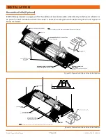
Page 13: ... drilling and screwing self tapping retention zip screws REFLECTOR OVERLAP APPROX 8 REFLECTOR END CAP ADJUSTABLE VENT ADAPTER S 20 AND LONGER LOOSE SCREWS ADJUSTABLE VENT ADAPTER S 20 AND LONGER TIGHT FASTEN END CAP WITH SCREWS SCREWS LOOSE SCREWS BEND TAB OVER END OF TUBE TIGHT SCREWS INSTALL BAFFLE S AS REQUIRED IN THE LAST SECTION OF TUBE OR AS SPECIFIED IN THE MANUAL CLOSE ALL OPEN ENDED S HOO...

Page 14: ...RNER ASSEMBLY NOTE CLOSE ALL OPEN ENDED S HOOKS CHAIN LINKS AND TURNBUCKLES OR ANY OPEN CONNECTION INSTALL BAFFLE S AS REQUIRED IN THE LAST SECTION OF TUBE OR AS SPECIFIED IN THE MANUAL BEND TAB OVER END OF TUBE ADJUSTABLE VENT ADAPTER S 20 AND LONGER LOCATE TUBE AND REFLECTOR HANGERS EVERY 10 THEREAFTER 10 FLANGED TUBE 10 TUBE 10 TUBE NOTE 30 SYSTEM SHOWN HERE THE SAME PRINCIPLE SHOULD BE FOLLOWE...

Page 15: ...ints in the structure It is required that the first 2 hangers be about 8 to 9 away Thereafter 10 apart on average is acceptable for the remainder of the heat exchanger At no time should hangers be more than 12 apart see Figure 8 Install the tube and reflector support hanger on the chain with Quick Links or S hooks refer to Figure 7 and Figure 8 I BEAM I BEAM CONCRETE BEAM TRUSS 24 MIN BEAM CLAMP T...

Page 16: ... seam must face down refer to Figure 9 for more details Figure 9 Installation of First Section of Flanged Tube COUPLING SHOULD BE LOOSELY FITTED 10 8 9 10 3 6 COMBUSTION TUBE TUBE REFLECTOR HANGERS LOCATE TUBE AND REFLECTOR HANGERS EVERY 10 THEREAFTER NOTE CLOSE ALL OPEN ENDED QUICK LINKS CHAIN LINKS AND TURNBUCKLES OR ANY OPEN CONNECTION INSTALL J BOLT AT FIRST HANGER TUBE FLANGE TUBE WELD SEAM F...

Page 17: ...LOCKOR 2 O CLOCK POSITION TO AVOID CONTACT WITH THE REFLECTOR REFLECTOR HANGER INSTALLATION OF REFLECTOR HANGERS AND J BOLT TUBE WELD SEAM TUBE WELD SEAM PLACE TUBE IN THE REFLECTOR HANGER AS SHOWN INSTALL J BOLT TO TIGHTEN CRADLE LOOP AT FIRST HANGER ONLY COUPLING INSTALLATION MOVING BETWEEN THE FOUR BOLTS TIGHTEN EACH ENSURING THAT EQUAL PRESSURE IS APPLIED TO EACH SET PIN IN TURN INSTALLATION O...

Page 18: ...mall tab on the baffle is folded over the end of the tube and clamped in place by the vent connector and vent system refer to Figure 13 Note Baffles are always placed at the end of the last heat exchanger tube length with the exception to the special configuration 205 000 BTU hr with a 50 tube length refer to for more details Note Baffles are either one or two sections each section is 6 in length ...

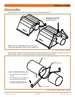
Page 19: ... OPEN CONNECTION Install reflector support brackets one at each reflector overlap position and one in the middle of each 10 reflector length Figure 15 shows the installation of the reflector support bracket Figure 15 Reflector Support Bracket Installation TUBE SPRING CLIP REFLECTOR BRACKET REFLECTOR BRACKET REFLECTOR SUPPORT BRACKET INSTALLATION 1 PLACE REFLECTOR BRACKET UNDERNEATH THE TUBE 2 HOOK...

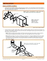
Page 20: ...6 HEATER END VENT TERMINATION END FASTEN ENDCAP WITH SCREWS TIGHT SCREWS LOOSE SCREWS LOOSE SCREWS REFLECTOR SUPPORT TIGHT SCREWS VENT TERMINATION END REFLECTOR SUPPORT LOOSE SCREWS TIGHT SCREWS LOOSE SCREWS TIGHT SCREWS FASTEN ENDCAP WITH SCREWS REFLECTOR OVERLAP APPROX 6 HEATER END NOTE DO NOT ALLOW TIGHTENED SCREWS TO PENETRATE REFLECTORS REFLECTOR OVERLAP ILLUSTRATION REFLECTOR OVERLAP APPROX ...

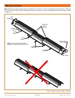
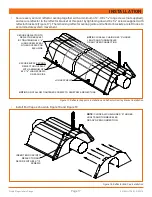
Page 21: ... Reflector Overlay Bracket Installation LOOSE SCREWS SECURE REFLECTOR TO REFLECTOR BRACKET BY TIGHTENING 8 X 4 LONG SCREW EVERY OTHER OVERLAP ON EACH SIDE SECURE EVERY SECOND REFLECTOR OVERLAP WITH A MINIMUM OF 2 8 X 8 LONG SCREWS ON EACH SIDE NOTE CLOSE ALL CHAIN LINKS S HOOKS J BOLTS AND TURNBUCKLES OR ANY OPEN CONNECTION NOTE DO NOT ALLOW TIGHTENED SCREWS TO PENETRATE REFLECTORS Install End Cap...

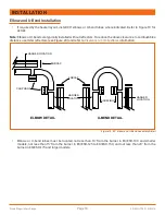
Page 22: ...rance to combustibles distance use miter reflectors see Figure 20 and refer to Clearance to Combustibles information ENDCAP COUPLINGS HANGER LOCATION HANGER LOCATION ENDCAP HANGER LOCATION COUPLINGS ELBOW DETAIL U BEND DETAIL Figure 19 90 Elbow and U Bend Assembly Detail Elbows or U bend tubes must be located not less than 10 from the burner in ES ESH 100 and smaller models not less than 15 from t...

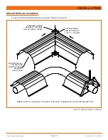
Page 23: ...ed Reflector as shown below in Figure 20 Figure 20 Mitered Reflector Installation ASSEMBLE CORNER BRACKET TO MITERED REFLECTORS AS SHOWN FASTEN MITERED REFLECTORS WITH 4 8 X 8 SCREWS MITERED REFLEC TOR SECTIONS SHOULD OVERLAP STANDARD REFLECTORS NOTE CLOSE ALL CHAIN LINKS S HOOKS J BOLTS AND TURNBUCKLES OR ANY OPEN CONNECTION ...

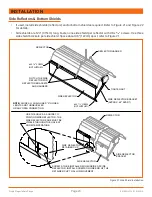
Page 24: ...ECTOR SIDE REFLECTOR SIDE REFLECTOR BRACKET APPROX 48 APART TIGHTEN NUT REFLECTOR SIDE REFLECTOR BRACKET SIDE REFLECTOR SIDE REFLECTOR RETAINER CUP 8 X 3 8 SCREW NOT SUPPLIED 8 X 3 8 SCREW NOT SUPPLIED NOTCH THE SIDE REFLECTOR FOR REFLECTOR BRACKETS AND HANGERS NOTE CLOSE ALL CHAIN LINKS S HOOKS J BOLTS AND TURNBUCKLES OR ANY OPEN CONNECTION USE THE HOLE AS A GUIDE TO POSITION SIDE REFLECTOR THE S...

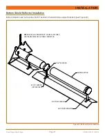
Page 25: ...ion Bottom shields need not overlap Each 5 section is held with two support brackets see Figure 22 TIGHTEN SCREW TUBING SECTION SUPPORT BRACKET BOTTOM SHIELD NOTE CLOSE ALL OPEN ENDED S HOOKS QUICK LINKS AND TURNBUCKLES OR ANY OPEN CONNECTION 8 X 8 SCREWS NOT SUPPLIED Figure 22 Bottom Shield Installation ...

Page 26: ...LD WITH SCREWS FROM OUTSIDE DECORATIVE GRILLE CROSS STRAP FASTEN WITH SCREWS AT EVERY 5FT SECTION NOTE CLOSE ALL CHAIN LINKS S HOOKS J BOLTS AND TURNBUCKLES OR ANY OPEN CONNECTION INSTALL END CAP AS USUAL DECORATIVE GRILLE END ANGLE FASTEN TO END CAP DECORATIVE GRILLE SUPPORTS Figure 23 Decorative Grille and Heater Installation 2 MIN DECORATIVE GRILLE PANEL T BAR SUSPENDED CEILING REFLECTOR SHIELD...

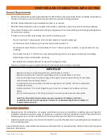
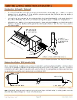
Page 27: ...ntally or vertically Un Vented Operation Requirements for combustion air supply and dilution air vary by jurisdiction building type and specific installation details See local codes for guidance In general fresh air ventilation must be provided to the building space at 4 cfm per 1000 BTU hr in the US 3 cfm per 1000 BTU hr in Canada Optional outside air supply is not recommended for un vented heate...

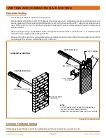
Page 28: ...le walls use approved vent terminal Tjernlund VH1 4 or deflector vent terminal with an approved insulating thimble When venting through non combustible walls use deflector vent terminal Recommended extension of the terminal past the outside wall surface is 18 minimum 18 MIN 4 VENT TERMINAL PN V CT011 NON COMBUSTIBLE WALL MAX 30 WITH 2 ELBOWS COMBUSTIBLE WALL 4 VENT TERMINAL MAX 30 WITH 2 ELBOWS 4 ...

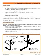
Page 29: ...in the vent pipe Insulation and additional sealing measures high temperature silicone at all seams may be required Common Vertical Venting Common vent sizing information is defined in the appropriate gas installation code Refer to ANSI Z223 1 and CSA B149 1 for sizes and installation information Connection locations to the common vent should be offset to avoid pressure interferences between heater...

Page 30: ...utdoor Installation ESH Models Only When a heater is to be mounted outdoors it must be installed in such a way that wind will have minimum effect on its movement This consideration is intended to eliminate undue stress on the gas flex connector In all cases a fresh air hood must be used in conjunction with a vent terminal of the approved type and all connections must be sealed with a high temperat...

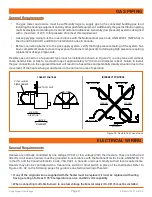
Page 31: ...install the gas connection in the approved manner will result in a hazardous and potentially deadly situation due to the movement of the heat exchanger and burner in the normal course of operation SHUT OFF VALVE 12 AIR FLOW DIRECTION HEATER MOVEMENT 0 180 CORRECT POSITIONS 3 7 62 cm MAX DISPLACEMENT HEATER MOVEMENT HEATER MOVEMENT HEATER MOVEMENT HEATER MOVEMENT INCORRECT POSITIONS WRONG WRONG Fig...

Page 32: ...R L1 120V TH PSW V1 IND L1 24V V2 GND S1 HV D D T STAT WHEN CONNECTION 120 VAC STAT THE TWO BLUE WIRES USED FOR THE 24VAC STAT MUST BE CONNECTED INTERNALLY 120V THERMOSTAT OPTIONAL EXTERNAL LED CNE DSI MODULE GAS VALVE YELLOW YELLOW YELLOW BROWN BROWN PURPLE PURPLE PURPLE RED RED ORANGE BLACK BLACK PINK GREEN BLUE BLUE RUN LAMP AIR SWITCH BLOWER SENSOR IGNITER BURNER NEUTRAL 24V TRANSFORMER L1 120...

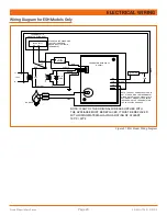
Page 33: ...R IND 120L FS 24V ORANGE BLACK BLUE N L1 BLACK NOTE THE POST PURGE FEAUTURE IS NOT UTILIZED WITH THE THERMOSTAT WIRED ON THE 120 VAC CIRCUIT THIS OPTION ONLY WORKS IF THE HEATER IS WIRED WITH THE THERMOSTAT ON THE 24 VAC CIRCUIT ABOVE PINK YELLOW NOTE IF ANY OF THE ORIGINAL WIRE AS SUPPLIED WITH THE APPLIANCE MUST BE REPLACED IT MUST BE REPLACED WITH WIRING MATERIAL HAVING A RATING OF ATLEAST 105 ...

Page 34: ...ws the products of combustion to be removed from the heat exchanger to avoid nuisance condensation and increase heat exchanger life When using a line voltage thermostat and the heat requirement has been met and the thermostat opens the burner and fan shut off with no post purge Maintenance For best performance certain minimal maintenance procedures should be performed before each heating season Be...

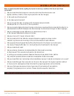
Page 35: ...wn in the manual e g One at each overlap and one in the middle of each reflector F Did you place the turbulator flue baffle in the flue end of the heater as mentioned in the manual Keep baffle tube 6 o clock and bend as mentioned in the manual F Did you install end caps F Did you observe clearance to combustibles for this model according to the manual This can also be found on the burner box F Is ...

Page 36: ...n module may be faulty Burner Does Not Light Is spark visible through site glass during ignition trial If not further electrical checks by a qualified service person are required Check to see if gas lines were properly purged of air Check inlet and outlet gas pressure during ignition period Burner Does Not Stay Lit Check ground wire continuity Check insulation on the igniter leads Measure flame si...

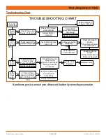
Page 37: ...L SRP REPRESENTATIVE Verify Sense Electrode Verify Ground Verify Wiring Does 24V Occur At Valve During Ignition Trial Check Wiring and Rectify As required Check Electrode Gap Set to 1 8 Replace Motor If Required Check 120V Power Verify at Motor Is There A Flame Signal To Module Min 0 8 Micro Amps Is Gas Present At Valve Is Gas Pressure Sufficient Check Ignition Wire Replace If Damaged Check Thermo...

Page 38: ...odels 40 000 to 175 000 BTU FA CE013 Blower for Models 205 000 to 220 000 BTU 6 P CH007 Blower Gasket 7 P CE003 Flame Sensor Electrode 8 P CE002 Spark Electrode 9 P CE006 Ignition Wire 10 P UG001P Burner Cup P UG007 Burner Cup Assembly C W Electrodes 11 P CH011 Sight Glass Assembly 12 P CE020 Air Switch 40 000 60 000 BTU Models P CE021 Air Switch 80 000 100 000 BTU Models P CE024 Air Switch 125 00...

Page 39: ...chase In no event shall the Manufacturer be liable for incidental expense or consequential damages of any kind This warranty does not cover any shipping installation or other costs incurred in the repair or replacement of the product No materials will be accepted for return without authorization This warranty will not apply if in the judgment of the Manufacturer the equipment has been improperly i...

Page 40: ...ES ESH LT209_10162019 315 N Madison Street Fortville IN 46040 317 577 0337 800 874 3285 sales advancedradiantsystems com www AdvancedRadiantSystems com ...

Reviews: