


Page 2
ES/ESH-LT209_10152019
Single Stage Unitary Range
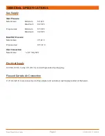
GENERAL SPECIFICATIONS
Gas Supply
Inlet Pressure
Natural Gas:
Minimum
5.0" W.C.
Maximum
14.0" W.C.
Propane Gas
Minimum
11.5" W.C.
Maximum
14.0" W.C.
Manifold Pressure
Natural Gas:
3.5" W. C.
Propane Gas:
10.5" W. C.
Inlet Connection
Natural Gas:
1/2" (12 mm) NPT
Electrical Supply
120 VAC, 60 HZ, 1 Amp: 36" (90 cm) cord with grounded 3-prong plug
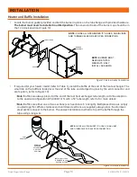
Flue and Outside Air Connection
4" (110mm) O.D. male connection for flue adapter and outside air (optional) provided at the heater.
Summary of Contents for ES/ESH Series
Page 2: ......


