March 1, 2002 Page E8
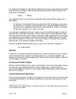
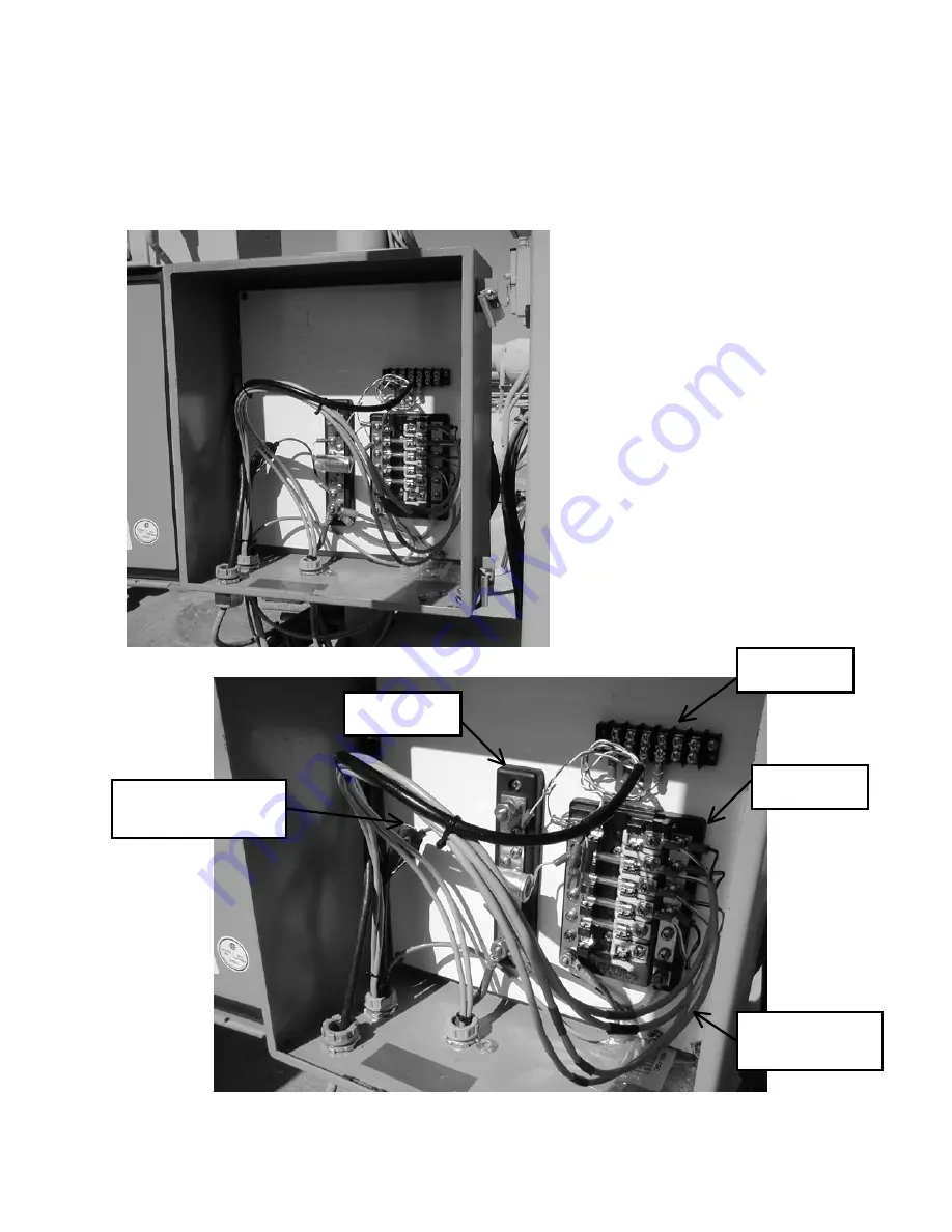
The upper barrier strip terminates the shielded/outdoor CAT 5 cable (black jacket) which is the least
expensive multi pair cable we could find. One pair is connected between the ground block and the DC+
bus on the fuse block for power supply remote sensing, a second pair is reserved for the future telemetry
application and the other two pairs are spares.
The incoming ground & DC- cable is attached
to the bottom of the ground block along with
ground leads to the negative bus on the fuse
block and the enclosure’s ground lug.
The incoming DC+ cable is attached to the
bottom of the DC+ bus on the fuse block.
Cables to the individual ARCi Hub antennas
(light gray) terminate on the right side of the
fuse block. The electrolytic capacitor (2200
uFd) across the power supply busses reduces
transients when individual Hub power
connectors are inserted or removed with
power on.
Space is provided at the top of the box for
lightning protectors which have not proven
to be necessary at our test site in San Jose,
CA.
Figure E7
Fuse Block
Ground Bus
Ground Connection
for CAT 5 shield
Power cables to
individual Hubs
Barrier Strip
Summary of Contents for AR1255
Page 4: ...March 1 2002 Page A1 A Table of Contents ...
Page 6: ...March 1 2002 Page B1 B Introduction C t t ...
Page 9: ...March 1 2002 Page C1 C System Description ...
Page 18: ...March 1 2002 Page D1 D Antenna and Frequency Planning ...
Page 24: ...March 1 2002 Page E1 E Hub Installation Detail ...
Page 29: ...March 1 2002 Page E6 Figure E4 Hub Antenna and Cable Installation Cable Access ...
Page 40: ...March 1 2002 Page F1 F Subscriber Inst l Details ...
Page 46: ...March 1 2002 Page G1 G Link Budget Parameters ...


