March 1, 2002 Page E11
Hub Installation Detail
Installation Detail – Indoor Equipment
Grounding
Proper grounding is critical to the safety, performance and the life of the equipment installed at
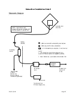
the hub. Refer to the
Schematic Diagram – Indoor Equipment
on the preceding page. ARCi
recommends that the installer follow the general grounding practices employed in cellular and PCS
hub sites.
ARCi recommends the following Lightning Protectors from PolyPhaser Corp.
(
www.polyphaser.com
). These PolyPhaser devices are designed to be bolted directly to the
ground bus.
75 ohm RG-6 transmit and receive cable
IS-75F-C1
Remote DC voltage sense
IS-SPDDL
RS-485
telemetry
IS-SPHSD
The ground bus, in turn, should be connected with an appropriate conductor (minimum #6 AWG)
to the hub site ground that includes the power service and building common ground, per the NEC
and local codes.
ARCi recommends the installer run a minimum #6 AWG conductor between the equipment room
ground bus and a common ground point adjacent to the hub antenna(s) unless the antenna
mounting system consists of a known low impedance ground (as a steel tower or monopole). In
the case of a single sector ARCi installation, this point can be the antenna ground bolt or
mounting bracket. In a multi sector ARCi installation including an ARCi outdoor junction box
(OJB) this conductor can be connected to the ground bus in the OJB, which in turn, is connected
to each hub antenna and any nearby building or support structure ground.
Normally the WMTS, upconverter(s), DC power supply, 100baseT data switch, etc. are mounted in
a 19-inch equipment rack in the hub equipment room. This rack should also be connected to the
ground bus, preferably by a conductor #6 AWG or greater.
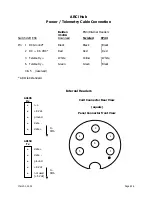
When shielded cable is utilized to connect DC power, voltage sense, and/or telemetry between the
hub equipment room and the hub antenna, ground the shield to the ground bus in the equipment
room.
DC Power
The ARCi hub antenna requires 8.5 Vdc +/- 0.5 volts at the hub antenna and draws approximately
950 mA.
Summary of Contents for AR1255
Page 4: ...March 1 2002 Page A1 A Table of Contents ...
Page 6: ...March 1 2002 Page B1 B Introduction C t t ...
Page 9: ...March 1 2002 Page C1 C System Description ...
Page 18: ...March 1 2002 Page D1 D Antenna and Frequency Planning ...
Page 24: ...March 1 2002 Page E1 E Hub Installation Detail ...
Page 29: ...March 1 2002 Page E6 Figure E4 Hub Antenna and Cable Installation Cable Access ...
Page 40: ...March 1 2002 Page F1 F Subscriber Inst l Details ...
Page 46: ...March 1 2002 Page G1 G Link Budget Parameters ...


