March 1, 2002 Page E13
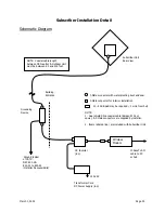
The upconverter is adjusted to provide the downstream signal at the center frequency appropriate
for the ARCi hub transmitter to create the desired RF carrier frequency. See Table D1 in the
Antenna and Frequency Planning
section of this manual for more information. The output of the
upconverter is connected with RG-6 cables through a 12 dB tap, and thence through the lightning
protector to the cable to the ARCi hub antenna.
The 12 dB taps provide negligible attenuation to the signal passing through and “copy” of the
signal 12 dB lower in level to the tap port. These are utilized for inserting a spectrum analyzer for
system set-up and maintenance without disturbing the normal connections.
Receive (Upstream) Signal Path
The upstream signal from the ARCi hub antenna is connected through the lightning protector and
through the 12 dB tap to the upstream port of the WMTS.
Summary of Contents for AR1255
Page 4: ...March 1 2002 Page A1 A Table of Contents ...
Page 6: ...March 1 2002 Page B1 B Introduction C t t ...
Page 9: ...March 1 2002 Page C1 C System Description ...
Page 18: ...March 1 2002 Page D1 D Antenna and Frequency Planning ...
Page 24: ...March 1 2002 Page E1 E Hub Installation Detail ...
Page 29: ...March 1 2002 Page E6 Figure E4 Hub Antenna and Cable Installation Cable Access ...
Page 40: ...March 1 2002 Page F1 F Subscriber Inst l Details ...
Page 46: ...March 1 2002 Page G1 G Link Budget Parameters ...


