March 1, 2002 Page F2
Subscriber Installation Detail
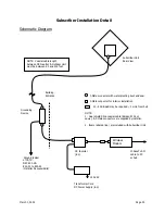
Schematic Diagram
Subscriber Unit
Rear View
Building
Entrance F-Male connector with waterproofing boot and seal
F-Male connector for interior installation
10 - 20 dB pad may be required < 1 mile from hub
Grounding
Device NOTE:
1. Dual shield RG-6 coaxial cable (Belden 9116 or
equiv.) & F-Male connectors are supplied by installer.
2. Items labeled (inc.) are included with Subscriber Unit
DC Inserter 10baseT LAN
(inc.) cable to PC
Ground typical or hub
of CATV…
NEC 810.2 &
820.33 to 820.42
(Installer Responsibility)
120 VAC
Transformer Cord
DC Power Supply (inc.)
Wireless
Modem
NOTE: Coaxial cable length
between DC Inserter & Outdoor Unit
must be between 50 and 200 feet.
Summary of Contents for AR1255
Page 4: ...March 1 2002 Page A1 A Table of Contents ...
Page 6: ...March 1 2002 Page B1 B Introduction C t t ...
Page 9: ...March 1 2002 Page C1 C System Description ...
Page 18: ...March 1 2002 Page D1 D Antenna and Frequency Planning ...
Page 24: ...March 1 2002 Page E1 E Hub Installation Detail ...
Page 29: ...March 1 2002 Page E6 Figure E4 Hub Antenna and Cable Installation Cable Access ...
Page 40: ...March 1 2002 Page F1 F Subscriber Inst l Details ...
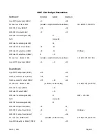
Page 46: ...March 1 2002 Page G1 G Link Budget Parameters ...


