March 1, 2002 Page F4
Cable Connection and Grounding
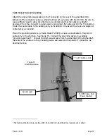
Attach the single RG-6 coaxial cable to the F connector on the rear of the subscriber ODU.
Waterproof the connection using a suitable method such as taping with Scotch #88. Be sure to
leave sufficient slack to allow the antenna to be oriented and that the cable runs directly
downward from the connector to avoid water running down the cable and into the F connection.
Route the coaxial cable to the building entry point utilizing UV-resistant tie-wraps and staples or
cable clamps as required.
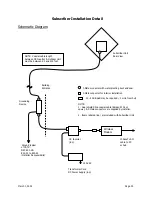
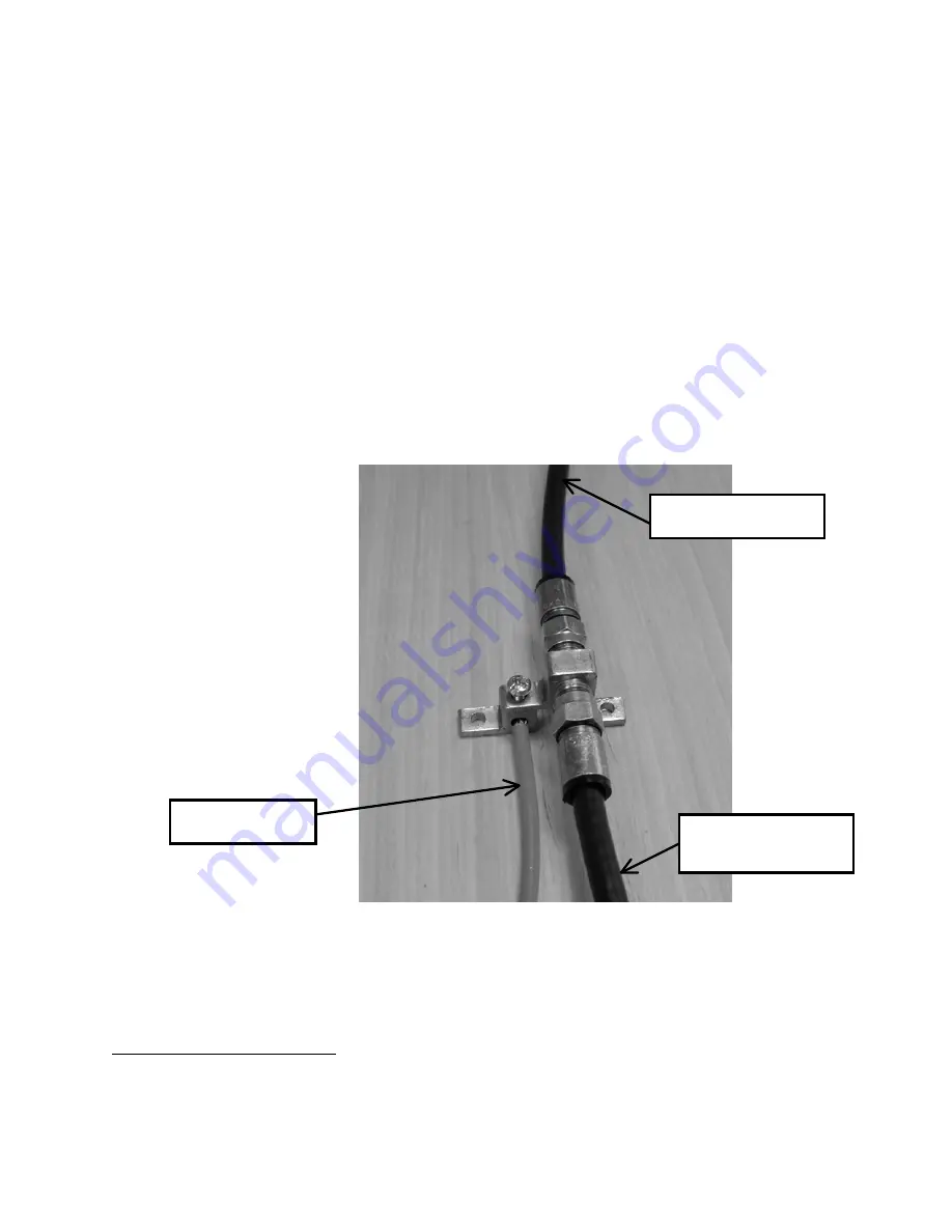
Mount the grounding device (e.g. Radio Shack 15-909C) as near as practicable to the point of
cable entry to the structure. See Figure F3. Connect the grounding device to a suitable
“grounding electrode”.
2
Connect the RG-6 coaxial cable from the subscriber ODU and the RG-6
that enters the structure to the grounding device and waterproof all exterior F connectors as
described above.
2
The National Electric Code, sections 820-33 and 820-40, describes this requirement in detail.
Figure F3
Grounding device
Ground Lead
To CPE Outdoor Unit
To CPE Indoor Unit
(Power Inserter)
Summary of Contents for AR1255
Page 4: ...March 1 2002 Page A1 A Table of Contents ...
Page 6: ...March 1 2002 Page B1 B Introduction C t t ...
Page 9: ...March 1 2002 Page C1 C System Description ...
Page 18: ...March 1 2002 Page D1 D Antenna and Frequency Planning ...
Page 24: ...March 1 2002 Page E1 E Hub Installation Detail ...
Page 29: ...March 1 2002 Page E6 Figure E4 Hub Antenna and Cable Installation Cable Access ...
Page 40: ...March 1 2002 Page F1 F Subscriber Inst l Details ...
Page 46: ...March 1 2002 Page G1 G Link Budget Parameters ...


