background image


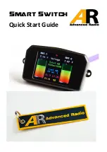
Smart Switch  

Quick Start Guide 

Summary of Contents for Smart Switch

Page 1: ...Smart Switch Quick Start Guide ...

Page 2: ...pplied with the Smart Switch should be protected from vibration Before installation please ensure that your batteries are fully charged The smart switch relies on this to know how much you have used in each pack WARNING The Smart Screen shows you how much you have used out of each pack and displays this as an indicator on the Smart Screen NEVER FLY WITH BATTERY PACKS THAT HAVE 35 OR LESS CAPACITY ...

Page 3: ...tuation This means you get the maximum capacity out of both batteries all the time 2 x 25 amp independent circuits Smart Switch is 2 x 25amp circuits into a high power matching battery redundancy circuit Smart Switch actually uses 4 x 50 amp rated FET circuits for battery power matching We passively rate the Smart Switch at 25amps per circuit Available as standard with JR In Out Futaba In Out Ultr...

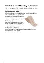
Page 4: ...3M tape we recommend clean ing both surfaces you wish to use the 3M tape on with isopropyl alcohol or methylated spirits Wait a moment for this to dry Once both surfaces are clean start by peeling the protective film off one side of the tape and placing this side on the switch Once you are happy with this peel the protective film off the other side of the 3M tape and place where desired With the p...

Page 5: ...art Display provides little to no protection against vibration Use this method if you are using a non vibration model or only where there is little to no vibration AVOID MOUNTING IN HIGH VIBRATION AREAS VIBRATION DAMAGE IS NOT COVERED UNDER WARRANTY Option 1 Using the remaining pieces of 3M clear tape we can mount the back of the screen to a surface NOTE This is a semi hard mount and will provide ...

Page 6: ... Red OutPut Cable Yellow OutPut Cable Self Balancing Receiver Battery 1 Self Balancing Receiver Battery 2 Smart Switch with 2 inputs and 2 outputs Receiver 1 Battery Input Red Input Cable BLUE LED Blue Cable Red OutPut Cable Dual Receiver Receiver 2 Battery Input Smart Switch Connection Guide Input Connectors Output Connectors Ultra Female JR Type Male Ultra Male JR Type Female Yellow Input Cable ...

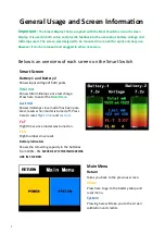
Page 7: ...Shows total milliamps since last charge Press here to enter the Main Menu Last mA Shows milliamps since model has been pow ered resets when model is turned off Press here to reset flight timer and Last mA FL T Flight timer since model was turned on FL N Flight number since reset Battery Indicators Shows the remaining capacity in the batteries from 100 0 NEVER FLY IF THE INDICATORS ARE IN THE RED M...

Page 8: ...w to set this in the First Time Setup section on page 10 Bat Capacity mA Shows the capacity of the batteries you are us ing We will go through how to set this in the First Time Setup section on page 10 Display Style Switch between Battery or Bar images on the smart screen For more information see additional screens on page 13 System Return Takes you back to the previous screen Calibrate Takes you ...

Page 9: ...en information page located on page 7 of this manual Step 1 Ensure that both batteries are plugged into the Smart Switch You will also need to en sure the smart display is plugged into the switch as it is used for programming Upon start up you will see the AR logo After a few seconds the Smart Screen will be shown Step 2 Using your finger press the green Total mA text on the smart display Step 3 Y...

Page 10: ...y important Please en sure the capacity is set correctly to the battery packs you are using Step 6 Once you have set these up press the RETURN button to take you back to the main menu Press RETURN again to go back to the Smart Screen You have successfully setup the Smart Switch Important The Smart display shows how much capacity you have left using the battery indicators on the left and right of t...

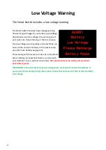
Page 11: ...emistry in the power setup area for more details see page 10 This warning will show every 4 seconds on the Smart Screen letting you know that there is an issue with your batteries If you see this screen show We recommend you do not fly and you check your battery packs IMPORTANT The Smart Switch has been designed to work with 2S and 3S chemistries If you receive this warning during setup please che...

Page 12: ... the Smart Display may become mis aligned with the touch pad Screen calibration is used to realign the touch screen with the display Note Before starting find something with a fine point avoid using sharp items Step 1 Using the Smart Display go into the sys tem menu once here press the Calibrate button Step 2 A warning and instructions will appear on screen Please Read this as it is an important p...

Page 13: ...he right If you want to return to the smart screen simply press the center of the display Display Style At the bottom of the Power Setup screen is an item called Display Style With Smart Switch we have included 2 different battery indicators that can show on the main smart screen These images provide a quick indication of the amount of capacity remaining in the battery packs you are using These di...

Page 14: ...witch and use a power distribution What are the 2 battery bar pictures on the front screen for These pictures show you a percentage of the battery you have left They will range from 100 to 0 and update as the battery packs are used Never fly if the packs are in the RED ZONE If I change the batteries in my model or move the Smart Switch to a different model will I have to setup the switch again Yes...

Page 15: ...ed to any warranty claim An over voltage or over current usage be yond stated specification Damage due to system failure negligence abuse accident im proper installation vibration damage damage to improper mounting or freezing Loss of time inconvenience loss of model or other incidental or consequential damages Contact Information Advance Radio and Booma RC sales boomarc com PO BOX 1 Oak Flats NSW...

Reviews: