background image


Advanced Telemetry Systems, Inc.          R4500S Reference User Manual          R05-11-A 

12

to the next screen.  If Screen 1 is needed at any time during the following screens, pressing 

ESC

 will bring the 

Frequency Entry Mode back to the first screen “Freq Entry Mode:”


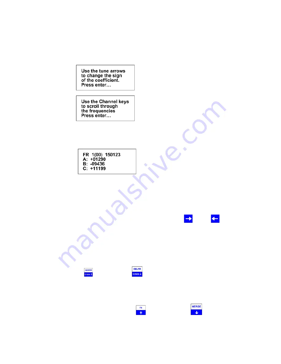
Screen 2 


Screen 3 


After the instructions, the screen will change for entering the frequency and coefficients.  The calibration data for 
each transmitter will be unique, and each frequency entered will have different coefficients to enter. 


Screen 4 


 FR 

1

 indicates frequency table 1.   


 (00)

 represents the first frequency in the list.  The next frequency will be FR 1(01), and so on. 


A, B,

 and 

C

 represent values for the second order regression equation mentioned earlier. 


The cursor defaults to the 1 MHz position for entering the frequency.  Use the

 and the 

 keys to move the 

cursor to the digit that needs changing.  When a number is entered in one location, the cursor will move to the right 
by one.  Pressing enter will store the frequency, and move to the next frequency position in the table.  When all the 
frequencies are entered, the screen will jump back to the start of the Frequency Entry Menu. 
 
 
If you have overlapping frequencies (i.e. 148.000-151.999), move the cursor to the 10 MHz position and then enter 
the desired numeric value. 
 

You may use the CHAN up  

   and CHAN down 

 keys at any time to scroll through the channels. These 

keys can be used to make corrections or change an individual channel frequency.  


After entering the frequency, press 

ENTER

.  Then the coefficients can be entered.  Entering the coefficients will 

be in order from A to B to C.  To change to the next coefficient, press 

ENTER

.   

To change the sign for the coefficient use the tune up 

 or the tune down key 

, a number other than 00000 

will need to be first entered before either key can change the sign. 


Summary of Contents for R4500S

Page 1: ...Advanced Telemetry Systems R4500S Receiver Datalogger 12 table version for use with Standard Transmitters User Manual ...

Page 2: ...and for variable pulse rate transmitters For fixed pulse rate transmitters the R4500S uses a pattern matching algorithm to detect up to 3 user entered pulse rates To verify a pulse rate the pattern matching algorithm uses 4 pulses from the transmitter to verify the pulse rate which helps separate a transmitter signal from a noise pulses This is important to know for setting the correct scan time f...

Page 3: ...ry Defaults page 17 Stationary Defaults Fixed Pulse Rate page 17 Stationary Defaults Variable Pulse Rate page 20 2 3 Tx Type page 24 2 3 1 Fixed pulse rate page 24 2 3 2 Variable pulse rate page 25 2 4 Stat Hold page 25 2 5 Channel Delay page 26 2 6 Ext Data page 27 2 6 1 RDP Remote Data Platform page 27 2 6 2 Goes Geostationary Operational Environmental Satellites page 27 3 0 Main Menu page 29 3 ...

Page 4: ...cy to the Scan Table Used only in Aerial Mode page 52 9 0 DELFR Deleting Frequencies Used only in Aerial Mode page 53 10 0 MERGE Merging Frequency Tables Used in Stationary and Aerial Modes page 53 11 0 RECORD Recording Data Used only in Aerial and Manual Modes page 53 12 0 PC Downloading Data page 53 12 1 Establish communication between the R4500S and the Computer page 53 12 2 Com Port Settings M...

Page 5: ...A 5 16 0 Offloaded Data Format page 64 17 0 Charging the Batteries page 66 18 0 EXT External Data Output page 67 18 1 Data Format and Translation page 68 18 1 1 BINARY DATA page 68 18 1 2 GOES Translated Output Format page 69 APPENDIX I JULIAN DATE CALANDARS page 71 72 ...

Page 6: ...Advanced Telemetry Systems Inc R4500S Reference User Manual R05 11 A 6 Intentionally Left Blank ...

Page 7: ...IAL Designed for transmitter location using aircraft but can easily be used in any other vehicle While scanning a table usually a small scan time is used to cycle through the frequency table quickly and does not allow enough time for the R4500S to identify a pulse rate on each frequency To remain on a specific frequency for a longer period of time to allow the R4500S to identify the pulse rate Hol...

Page 8: ... for a comfortable level Its setting does not affect detection sensitivity Any monaural headset with a 0 25 inch jack may be used Most users prefer headsets with muffs to reduce external noise from wind or aircraft Inserting the headset jack disables the internal speaker The AUX connector is used to interface antenna switches or other controlled devices The SIG LED will light for every valid pulse...

Page 9: ...taneously with another key To stop a scan Aerial or Stationary stop a setup sequence or to return the previous menu press the ESC key Pressing the wrong key or entering invalid data will produce the response NOT an Option or Out of Range Upper Keypad Functions To access the upper keypad functions first press SHIFT and then press the upper function key sequentially MENU Enters the Main Menu SETUP E...

Page 10: ...r of frequency entries you will be using for the transmitters in this table Note the first channel is Channel 00 There are 50 channels available for each frequency table After entering the Chan Qty the screen will change to entering the frequencies Screen 2 The default frequency will be the lowest frequency of the receiver FR 1 indicates frequency table 1 00 represents the first frequency in the l...

Page 11: ...l take up the space used for entering one frequency the maximum number of frequencies that each table can store will now be 25 This calibration data will also be requested in the defaults menu when setting up your reference frequency if a reference transmitter is used The frequencies entered in the R4500S are 6 digit numbers For frequencies below 100 MHz the frequencies are entered as 5 digit numb...

Page 12: ...o move the cursor to the digit that needs changing When a number is entered in one location the cursor will move to the right by one Pressing enter will store the frequency and move to the next frequency position in the table When all the frequencies are entered the screen will jump back to the start of the Frequency Entry Menu If you have overlapping frequencies i e 148 000 151 999 move the curso...

Page 13: ... the Setup Menu To return to the Main Menu from the Setup Menu press ESC 2 1 Clock To access the clock position the cursor on Clock and press ENTER Here is an example of the Clock Menu You can press ENTER to go through each setting or use the and the keys to move forward or backwards to a specific setting To change the numeric value use the numeric digits on the keypad or you can use the and keys ...

Page 14: ...nt the numeric value up or down or to toggle between YES NO selections For the R4500S to accept a value press ENTER Moving the cursor with the or the will allow movement between screens or by pressing ENTER for the last item in the window to proceed to the next window Screen 1 Table Selects the frequency table used for scanning Twelve tables are available Multiple tables are used to optimize Aeria...

Page 15: ...D is pressed while not in Hold the frequency will not be recorded but the time stamp and GPS location will be stored to memory An optional GPS antenna must be connected to the R4500S for the GPS location option to work Screen 3 The number entered here should represent the total number of pulse rates you are using in your study There should not be more than one transmitter per frequency If you need...

Page 16: ...Recording data can be selected YES or NO for an Aerial Scan When Auto record is selected as YES for an Aerial Scan a data point will be stored for every valid pulse rate detected The time stamp frequency pulse rate signal strength and GPS location will be saved to memory for every valid pulse rate detected An optional GPS antenna must be connected to the R4500S for the GPS location option to work ...

Page 17: ...een YES NO selections For the R4500S to accept a value press ENTER Moving the cursor with the or the will allow movement between screens or by pressing ENTER for the last item in the window to proceed to the next window Screen 1 Continual The R4500S will continually scan through the selected frequency table Periodic The R4500S will scan through the selected frequency table only once and wait to sc...

Page 18: ...in its frequency table This feature allows faster scanning by truncating the scan time if no transmitter is detected in the Time Out period The user defines the parameter Range 001 300 seconds Refer to section 14 0 for information on setting the Time Out value Scan Time The amount of time to hold on a frequency and attempt to detect transmitters The Scan time will override the Time Out time if a p...

Page 19: ...cted to the AUX port of the R4500S if using more than 1 antenna If using a 2 way switchbox this would be set to 2 EXT Data XFER When this is enabled the receiver will dump the logged data out a serial port once an hour To change this option s settings use the Ext Data choice in the Setup Menu To activate the EXT Data XFER feature use the or the key These two keys are used to toggle between the two...

Page 20: ...7 00 am This means when the data are offloaded you may have the data for the actual transmitters appearing before the reference transmitter This is true even if the animal data were collected at 6 30 am and the reference data were collected at 6 00 am Stationary Defaults Variable Pulse Rate Move the cursor to the Stationary Default item and press ENTER There will be multiple windows to go through ...

Page 21: ...e Time Out period The Scan Time is set to whatever you need this set at Range 0000 1440 seconds Refer to section 15 0 for information on setting the Scan Time value A If Continual 1 was selected in screen 1 this will read Store Rate If Periodic 2 was selected in screen 1 this will read Log Period Store Rate This defines how often a transmitter s detection will be stored for each antenna Range 0000...

Page 22: ...er will dump the logged data out a serial port once an hour To change this option s settings use the Ext Data choice in the Setup Menu To activate the EXT Data XFER feature use the or the key These two keys are used to toggle between the two choices Screen 7 Reference Freq Pressing ENTER while the cursor is on NO will bring the screen back to the Default Menu To activate the Reference transmitter ...

Page 23: ...e the time of the first valid pulse rate detected Store Rate This defines how frequently the data from the reference transmitter will be stored Range 0005 1440 minutes A count of the number of detected pulse rates will be stored for the entire store rate Screen 9 Screen 10 The frequency cannot be changed in screen 8 Only the coefficients are to be entered here Entering the coefficients will be in ...

Page 24: ... if the pulse rate is valid given the information entered for the pulse rates before starting an Aerial Scan or a Stationary Scan Also the R4500S will check to see if the incoming pulse rates are within the tolerances entered for each pulse rate If the pulse rates do not match the entered information the pulse rate will be thrown out This Pattern Matching method helps to filter out noise pulses A ...

Page 25: ...ansmitter Temperature Ax2 Bx C x is the transmitter period A B and C are calibration constants and need to be entered for the to display converted data Move the cursor with the or the to choose what type of measurement data you want to collect and store and press ENTER 2 4 Stat Hold This time setting is only used only for a Stationary Scan and is not used for Hold during Aerial Scanning Stat Hold ...

Page 26: ...y time is set correctly Setting the Channel Delay time longer gives more time for the R4500S to set a new threshold and optimize sensitivity while at the same time ignoring noise Setting it longer than necessary means the additional delay will be added to every frequency channel scanned also increasing the time for all channels to be scanned Thus the goal is to set the delay so most but not necess...

Page 27: ... bits 1 stop bit Enter a 1 or 2 for the desired serial port settings and press ENTER The screen will return to the Setup Menu 2 6 2 Goes Geostationary Operational Environmental Satellites With this setting selected limited amounts of data collected during the hour will be dumped out the PC CLONE and AUX serial ports as binary compressed data The GOES functionality enables the receiver to send data...

Page 28: ...llite transmission you will need to make sure you have intervals where you collect limited data so the system can catch up Screen 4 Enter a numeric number from 1 to 255 and press ENTER When using pattern matching pulses are expected to be received at a certain fixed rate Those pulses occurring at that rate are considered matches Any pulses that are received in addition to the matches are considere...

Page 29: ...entially The latest time stamp and an accumulative count of the detected pulses and consecutive pulse rates will be stored When the RECORD feature is activated Saving targets will flash in the display To change the frequency The cursor defaults to the 1 MHz position From here you can enter whatever frequency you are looking for You may use the or the keys to change the cursor position More likely ...

Page 30: ...etect transmitters Range 001 300 seconds For setting Scan Rate time see section 13 0 Auto Record Selects if transmitter pulse rates will be detected and automatically recorded by the R4500S The option of Auto Recording data can be selected YES or NO for an Aerial Scan When Auto record is selected as YES for an Aerial Scan a data point will be stored for every valid pulse rate detected The time sta...

Page 31: ...ough each setting in the Aerial Setup windows When all settings have been entered the Aerial scan will start The default settings are used to pre enter the values for each item listed for the Aerial Setup Pressing ENTER on these values stores them into memory If there needs to be any changes made to any of the items pressing ENTER will store the changed value into memory and that changed value wil...

Page 32: ...connected to the receiver the GPS functionality is turned on and a valid GPS fix has been acquired Period The Period will be displayed when a valid pulse rate has been detected The single digit number displayed after the period is a counter that loops from 0 9 The counter will increment when valid pulse rates have been detected Pulse Rate The Pulse rate will be displayed when a valid pulse rate ha...

Page 33: ... cursor with the or the will allow movement between screens or by pressing ENTER for the last item in the window to proceed to the next window Screen 1 Table Selects the frequency table used for scanning Twelve tables are available Multiple tables are used to optimize Aerial surveys in multiple locations Scan Rate Sets the amount of time the R4500S will stop on each frequency while attempting to d...

Page 34: ...e values stores them into memory If there needs to be any changes made to any of the items pressing ENTER will store the changed value into memory and that changed value will be used in the Aerial scan If the defaults settings are not used and a different value is entered the new value entered will be used for that Aerial Scan until the scan has been terminated If a new scan is started by starting...

Page 35: ...the Hold text will appear on the screen Use this key when you want to store data i e time frequency signal strength GPS location and pulse rate temperature etc for the displayed frequency If the signal is not being decoded and you still want to save GPS data frequency and time press SHIFT then RECORD Pressing the HOLD key again will cause the R4500S to resume scanning Note GPS data will only be st...

Page 36: ...values Change and enter the value you want to use for this one time scan only If you want the values to be remembered for future scans go back to the default menu and make the changes there Pressing ENTER while the cursor is on Resume Last Scan will start up your last scan using your last scan settings Screen 2 Table Typing a new table number and pressing ENTER will resume the last scan using just...

Page 37: ...e stationary scan 3 3 1 Starting a Stationary Scan Fixed Pulse Rate Transmitter From the Main Menu use the or the key to move the cursor to the STATIONARY position and press ENTER To change the numeric value use the numeric digits on the keypad or you can use the and keys to increment the numeric value up or down or to toggle between YES NO selections For the R4500S to accept a value press ENTER M...

Page 38: ...ating the scan time if no transmitter is detected in the Time Out period The user defines the parameter Range 001 300 seconds Refer to section 14 0 for information on setting the Time Out value Scan Time The amount of time to hold on a frequency and attempt to detect transmitters The Scan time will override the Time Out time if a pulse has been detected during the Time Out period The Scan Time is ...

Page 39: ...ntenna switchbox connected to the AUX port of the R4500S if using more than 1 antenna If using a 2 way switchbox this would be set to 2 EXT Data XFER When this is enabled the receiver will dump the logged data out a serial port once an hour To change this option s settings use the Ext Data choice in the Setup Menu To activate the EXT Data XFER feature use the or the key These two keys are used to ...

Page 40: ...e 0005 1440 minutes Note The data are not stored until the storage period has expired For example with storage period set up for once an hour the time the first data are collected might be at 6 00 am Although the data recorded will reflect 6 00 they will not be committed to memory until 7 00 am This means when the data are offloaded you may have the data for the actual transmitters appearing befor...

Page 41: ...ally resume the Stationary Scan when power is restored The values used for the Stationary Setup will still be stored in memory and they will be the values used when resuming the stationary scan To stop the Stationary Scan press ESC This will return the screen to the Program Menu If you desire to start the stationary scan after stopping the scan a new window will appear when entering the Stationary...

Page 42: ...ble Periodic The R4500S will scan through the selected frequency table and shut the power off for a period of time Screen 2 The number entered here should represent the range of pulse rates you are using in your study The available period range allowed to be entered is between 400ms to 6000ms The periods measured from signals that are outside the entered range will be thrown out Screen 3 A Store R...

Page 43: ...red in one 15 second scan time during the 10 minute scan period Stored with it will be a total number of pulses that the receiver determined to be pulse rates during the 10 minute store period along with the total number of pulses detected during the Store Period Log Period This defines the time interval between the receiver cycles where the R4500S performs one scan of the frequency table If the s...

Page 44: ...and the store rate of the reference transmitter After entering the reference frequency transmitter information the Stationary Scan will start Screen 8 Reference Freq This is the frequency of a transmitter set up within range of your station used as a check on the system Since you will not need the same quantity of data you can set up a longer store period to use up less memory Instead of the stron...

Page 45: ... changed and these default settings will be the settings used when the R4500S is turned back on after having been turned off Stationary Scan Window Variable Transmitter FRXX XX This represents the frequency table 1 table 1 the frequency channel number o3 4th channel number in table 1 and the 6 digit number following is the frequency the receiver is tuned to Time This is the Julian date and the hou...

Page 46: ... ENTER while the cursor is on Scan Using Defaults Scan the Stationary Scan will start up with the values entered in the Stationary Default Menu If any of the scan protocol values need to be changed you will need to move the cursor to New Scan and press ENTER The values in the list will show the default values Change and enter the value you want to use for this one time scan only If you want the va...

Page 47: ...ual antennas Any Signal Present The receiver tunes in the next frequency from the frequency table Timer 0 Monitor all the station s antennas and display Ant 0 Monitor the station s antenna s and display Ant 1 No No Yes Yes Start Timer Time Out Any Signal Present Any Signal Present Timer Time Out No No Yes Timer Scan Time Store any data found Timer Time Out Timer Scan Time Store any data found Time...

Page 48: ... frequency tables and default settings from one receiver to another The optional blue clone cable with male DB9 connectors on both ends is required to use this function Use the following procedure 1 Connect the Clone cable between the two receivers 2 Turn both receivers on 3 Select CLONE on the receiver you want to be the recipient of the data press ENTER The receiver should respond with If a conn...

Page 49: ...will also be mirrored in the Output along with the display line number The serial settings will be baud 9600 no parity 8 data bits 1 stop bit 5 0 TEST View of the Battery Voltage Pressing the SHIFT key followed by pressing the TEST key sequentially will display the receiver s power source voltage If the power source is the internal battery it will be the internal battery voltage If it is an extern...

Page 50: ...t of the data to be viewed will depend on the selected TX Type and whether it was Aerial or Stationary Logging Screen 1 Block The number of the first data block you want to view The first data block is zero Range This is the number of data blocks you want to scroll through Screen 2 This represents a block of saved parameter data that was used during the following data block saves It is not viewabl...

Page 51: ...since this GPS data had been recorded This sequence of screens will repeat until you have viewed all the data blocks listed in your range or you press the ESC key 6 3 Delete Data This instructs the R4500S to reset the data pointer back to the beginning of memory effectively deleting all the stored data blocks Screen 1 Screen 2 Screen 3 This message flashes momentarily then returns you back to the ...

Page 52: ...d there is a valid GPS fix GPS OFF The GPS is turned OFF NO FIX The GPS is attempting to acquire a valid GPS fix GPS ERR The GPS has not been able to get a valid GPS fix within 5 minutes NO GPS The GPS has not been able to get a valid GPS fix after 15 minutes If a valid GPS fix is found during NO FIX GPS ERR or NO GPS the indicator will change to a non flashing GPS indicator The GPS requires a cur...

Page 53: ...nce you exit the Stationary scan but maintained if you exit Aerial Mode and return to the Aerial Scan using the Resume Last Scan option 11 0 RECORD Recording Data Used only in Aerial and Manual Modes Pressing the SHIFT key followed by pressing the RECORD key sequentially activates the record feature This forces a save to be preformed when a save would not ordinarily be done The R4500S will save th...

Page 54: ...erial port on the computer and to the PC CLONE connector on the R4500S With the ATSWinRec program running on the computer move the R4500S cursor to the PC position while in the R4500S Program Menu Presses ENTER on the R4500S The R4500S display will change to And then to If communication is not successful 1 Check that both ends of the offload cable are plugged in The female end of your cable plugs ...

Page 55: ...e ATSWinRec program has the following command box that will appear in the center of the screen 12 3 1 First Time Start Up When starting the ATSWinRec program for the first time you will be prompted for a com port with the following dialog box It is also possible that you may also get the following dialog box ...

Page 56: ... A 56 This is a notification that the software has readjusted to the R4500S receiver model 12 3 2 Offloading Data If you select Offload Stored Data followed by OK the following screen then appears You can select some of the offload parameters Most are self explanatory ...

Page 57: ...greater than zero For example you may only want to check the most recent data You can select the coordinate for the GPS data You can select the frequency data displayed with all six digits or with the two most significant digits suppressed Showing parameters in the offloaded data will add scanning information for Aerial Stationary and Manual modes All scan parameters will be available for viewing ...

Page 58: ...to recover the last data set deleted The deleted data is only retrievable as a downloaded file using ATSWinRec 4 Next will be a window that prompts the user for a file name The default file name is a date stamped file name The file is stored in a Data folder The location will be where the ATSWinRec was installed to The default location is C Program Files Advanced Telemetry Systems Inc ATSWinRec_45...

Page 59: ... section 2 3 Defaults for information on each configuration parameter All default configurations can be retrieved from the receiver or from a file and sent to the receiver or saved to a file If no configuration was sent to the receiver or saved to a file selecting Close will not save any changed values When selecting the Set Receiver Clock to PC Clock button the PC time is sent to the R4500S and i...

Page 60: ...ing a file for a single frequency table ATSWinRec will be looking for a file with the extension _tbl csv A group table file file name with extension _grp csv will not be allowed to be opened If a file is saved as a single table the file can be loaded to any selected frequency table and sent to the receiver by selecting the corresponding frequency table checkbox When loading a single table from a f...

Page 61: ...nough time for multiple pulses and for the SIG LED to flash for every detected pulse 14 0 Setting Stationary Time Out The DSP needs two pulses to verify 1 pulse therefore the minimum stationary Time Out time must be set to allow for at least 2 pulses from the transmitter with the longest pulse repetition period to be detected Using the example above a 45 ppm transmitter will have a period length o...

Page 62: ...rate The R4500S uses a pattern matching algorithm to verify a pulse rate The pattern matching algorithm uses 4 valid consecutive pulses and the entered pulse rate information to verify a pulse rate A setting for 5 consecutive pulses is needed because the first pulse is not used The Scan Time should be greater than the minimum setting to help allow for filtering out false detections Noise can trigg...

Page 63: ...Advanced Telemetry Systems Inc R4500S Reference User Manual R05 11 A 63 ...

Page 64: ...ency TTT A number from 40 154 representing the signal strength NNN A number from 1 255 representing the number of pulses received during the recorded scan PPP A number representing the recorded pulse rate of the detected transmitter MMM A number from 1 255 representing the number of valid pulses during the store period Note This excludes estimated noise pulses and may include data calculated over ...

Page 65: ...ed for each data point that was recorded Each column has a short descriptive header Expand the columns to read what each parameter field is Below are the column headers followed by some examples Column Headers PrmNum Block_Type Scan_Type TimeOut Scan Tables GPS StoreRate Antennas ExtData Reference_Frequency Parameter Examples 0 Aerial Fixed PR Pattern Matching PR1 55 Tol 1 PR2 0 Tol 2 PR3 0 Tol 0 ...

Page 66: ...ommended to maintain a charge cycle when storing the receiver for long periods of time If the charge capacity of the batteries does not seem to be at full capacity a couple charge cycles can bring the battery pack back to full capacity discharge charge discharge charge The charger supplied with the R4500S is a smart charger There is a thermal sensor to detect a full charge and to shutdown the char...

Page 67: ... only This screen indicates the number of bytes that were sent over versus the number of bytes that the GOES transmitter sent acknowledges for If these numbers do not match a CHECK will flash on the screen indicating a probable system problem If this happens check your connections Also make sure your GOES transmitter is turned on and operating correctly The GOES transmitter should display the same...

Page 68: ...ata blocks You can connect to the PC CLONE from your PC using your offload cable By using a communication software such as Microsoft HyperTerminal or Symantec s Procomm Plus and the serial settings baud 9600 no parity 8 data bits 1 stop bit or baud 57600 no parity 8 data bits 1 stop bit you can monitor the data that is sent out This data comes out in a compressed format that if using GOES is the s...

Page 69: ...5 0 89 30 2 7 42 132 07 00 12 5 Fixed 35 15 54 0 87 14 1 7 22 132 07 00 12 5 Fixed 35 731 71 0 154 21 0 7 38 000 END Day A number from 1 366 representing the Julian day 1 366 for a leap year otherwise 1 365 This appears in the transmission header of R4500S and it indicates the day the data was processed for transmission Hr A number from 0 23 representing the hour This appears in the transmission h...

Page 70: ... variable and the data represents pulse period Freq A number representing the transmitter s frequency It will be a number from 0 9999 representing the last four digits of the frequency Pulse Rate Temperature Depth Altitude or Period ms The number representing the measured data Ant A number from 0 8 representing the antenna being used A 0 indicates all antennas were turned on Matches A number from ...

Page 71: ... 133 164 194 225 256 286 317 347 13 14 014 045 073 104 134 165 195 226 257 287 318 348 14 15 015 046 074 105 135 166 196 227 258 288 319 349 15 16 016 047 075 106 136 167 197 228 259 289 320 350 16 17 017 048 076 107 137 168 198 229 260 290 321 351 17 18 018 049 077 108 138 169 199 230 261 291 322 352 18 19 019 050 078 109 139 170 200 231 262 292 323 353 19 20 020 051 079 110 140 171 201 232 263 2...

Page 72: ...04 134 165 195 226 257 287 318 348 13 14 014 045 074 105 135 166 196 227 258 288 319 349 14 15 015 046 075 106 136 167 197 228 259 289 320 350 15 16 016 047 076 107 137 168 198 229 260 290 321 351 16 17 017 048 077 108 138 169 199 230 261 291 322 352 17 18 018 049 078 109 139 170 200 231 262 292 323 353 18 19 019 050 079 110 140 171 201 232 263 293 324 354 19 20 020 051 080 111 141 172 202 233 264...

Page 73: ...Advanced Telemetry Systems Inc R4500S Reference User Manual R05 11 A 73 ...

Reviews: