background image


Version 16.10 

AF-6600 AF-5000 Series Install Manual


151 

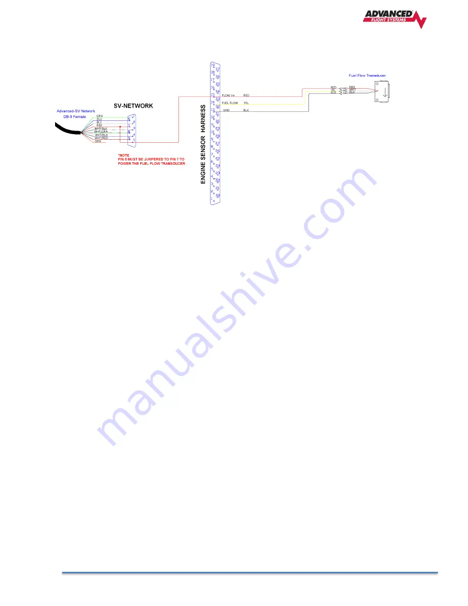
Fuel Flow Transducer Wiring


Summary of Contents for AF-5000

Page 1: ...emote Dynon SV EMS and SV ADAHRS modules This manual does not cover older AF 5000 systems with internal EMS or internal air data sensors March 2023 Experimental instrument limited to use in experiment...

Page 2: ...tored in any storage medium for any purpose without the express written permission of Advanced Flight Systems Dynon Avionics Advanced Flight Systems Dynon Avionics hereby grants permission to download...

Page 3: ...STATE TO STATE AND IN COUNTRIES OTHER THAN THE USA IN NO EVENT SHALL DYNON AVIONICS BE LIABLE FOR ANY INCIDENTAL SPECIAL INDIRECT OR CONSEQUENTIAL DAMAGES WHETHER RESULTING FROM THE USE MISUSE OR INAB...

Page 4: ...Version 16 10 AF 6600 AF 5000 Series Install Manual 4 Revision History REVISION DATE DESCRIPTION 16 10 3 15 2023 AF 6600 AF 5000 V16 10 Install Manual...

Page 5: ...___________ 26 3 3 SV MAG 236 Remote Magnetometer _________________________________________________ 29 ADAHRS 200 201 MAG 236 Magnetic Heading Calibration___________________________________________ 31...

Page 6: ..._____________ 134 EGT Clamp Installation _______________________________________________________________________ 134 Engine Tachometer RPM _____________________________________________________________...

Page 7: ...___ 184 Outside Air Temp OAT ______________________________________________________________________ 185 G Meter___________________________________________________________________________________ 186 R...

Page 8: ..._____________________ 225 APPENDIX B Electrical Connections ________________________________________________ 226 Advanced SV Network Wiring _________________________________________________________ 22...

Page 9: ...X W Harness Wiring Diagrams_____________________________________________ 262 P N 53600 EFIS Main Harness_________________________________________________________ 263 P N 538XX CHT EGT Harnesss _______...

Page 10: ...ynthetic Vision is a standard feature on the EFIS screens The AF 6600 has a flush mount LCD with a dual concentric encoder and light sensor for automatic dimming Each EFIS display has five 5 RS 232 se...

Page 11: ...mounted option When you install avionics in an aircraft you will need to wire to an avionics power bus with circuit protection and connect to different types of data buses so all the equipment can tal...

Page 12: ...ted pair data lines The spare 9th wire is used to provide power to the SV EMS 220 module for a connected fuel flow transducer Most of the Dynon components connect to the SV Network to talk to the EFIS...

Page 13: ...over Ethernet cable If you only have two EFIS screens in the aircraft panel you can use a single Ethernet cable to connect the screens together If you have a three EFIS screen panel or have the XM Wea...

Page 14: ...Version 16 10 AF 6600 AF 5000 Series Install Manual 14...

Page 15: ...ease of service the panel should have 6 32 PEM nuts or plate nuts installed for mounting the EFIS screens EFIS Screen Rear Connections Green Power ON LED Ethernet Amber Heart Beat LED 2 USB Ports EFIS...

Page 16: ...Version 16 10 AF 6600 AF 5000 Series Install Manual 16 1 5 System Block Diagram...

Page 17: ...rcraft has two Nav radios each one should be wired to a different screen for backup reliability If the aircraft has two GPS units each one should be wired to a different screen for backup reliability...

Page 18: ...ts should be wired to a good ground connection 5 Screen RS 232 Serial Port Wiring Using your block diagram wire the EFIS Screen s serial ports to the external equipment 6 Screen Digital Inputs and Out...

Page 19: ...Screen with all EFIS screens powered up 16 Calibrate the Trim and Flap sensors on PFD EFIS 17 Configure the Aircraft V Speeds on each screen This will need to be configured on each EFIS Screen in the...

Page 20: ...V NET 9 pin male connector that will plug into a SV NET 5 Port hub The EFIS Expansion 15 pin connector also contains the pins for RS 232 serial port 4 and the backup battery power to the EFIS The EFIS...

Page 21: ...Version 16 10 AF 6600 AF 5000 Series Install Manual 21 2 2 SV Network Wiring to AF 6600 AF 5000 EFIS with ACM 2 3 SV Network Harness Connections 2 4 SV Network SV EMS 220 Harness Connections...

Page 22: ...Color Description 1 Green Network Data 1 A 2 Black Network Ground 1 3 White with Black Stripe Network Ground 2 4 White with Blue Stripe Network Data 2 B 5 Orange EMS Auxiliary Voltage 6 Blue Network...

Page 23: ...AF 6600 AF 5000 Series Install Manual 23 3 Component Locating and Mounting Van s RV 14 AF 6600 IFR Panel Example 3 1 AFS EFIS Mounting and Panel Cutout AF 6600 AF 5600 Panel Cutout AF 6600 AF 5600 Sc...

Page 24: ...Version 16 10 AF 6600 AF 5000 Series Install Manual 24 AF 5700 Panel Cutout...

Page 25: ...Version 16 10 AF 6600 AF 5000 Series Install Manual 25 AF 5800 Panel Cutout AF 5500 Panel Cutout AF 5500 Screen Cut Out...

Page 26: ...is significantly linked to a proper ADAHRS installation The installation location must meet all of the mechanical magnetic orientation and environmental requirements detailed below ADAHRS with Respec...

Page 27: ...compass needle deviates significantly from magnetic North or cycles back and forth the location is not ideal for ADAHRS installation Advanced SV Network ADAHRS Installation Orientation An ADAHRS modul...

Page 28: ...terfere with outside air temperature readings such as Direct sunlight Engine heat and exhaust Aircraft interior back side of sensor Heated air from the cabin exiting from an open window or cabin air e...

Page 29: ...lds e g AC currents non constant DC currents and non stationary ferrous material such as electric turn coordinators and control surfaces Thus you must avoid mounting the module close to sources of dyn...

Page 30: ...the bottom of the aircraft The label on the SV MAG 236 s must be oriented towards the top of the aircraft The side of the SV MAG 236 where the cable exists must be oriented towards the nose of the air...

Page 31: ...rmal nose up ground attitude as long as the AF 5000 attitude display shows the correct corresponding nose up attitude A working GPS receiver must be connected to the AF 5000 system in order to calibra...

Page 32: ...und if one of the gauges is in the RED warning band or an input is configured to trigger the alarm The Alarm Output can be used to drive a master warning light on the panel If multiple screens are use...

Page 33: ...es power requirement is 12 volts at 3 Amps a 5 amp circuit breaker or fuse should be used for the system All wire should meet Mil Standard MIL W 22759 16 Tefzel insulation 20 AWG wire is normally suff...

Page 34: ...backup power input must be connected to the aircraft battery or a TCW backup battery module The backup power input keeps the clock time when shut down and prevents an EFIS reboot when starting the air...

Page 35: ...Version 16 10 AF 6600 AF 5000 Series Install Manual 35 EFIS TCW Backup Battery Wiring P N 71713 3 AMP hours for a single screen P N 71714 6 AMP hours for two screens...

Page 36: ...Version 16 10 AF 6600 AF 5000 Series Install Manual 36...

Page 37: ...hed audio input you will need to purchase a audio mixer Do not attempt to connect the EFIS audio to a music input on an intercom they are not the same impedance and it will not be loud enough Do not a...

Page 38: ...d wire colors Remember to configure the Advanced SV network after connecting all modules to a display ARINC 429 Device Connection Harness Construction Because the SV ARINC 429 can be connected to a va...

Page 39: ...serial input that is designed to provide auxiliary information that ARINC 429 GPS outputs do not provide such as altitude The EFIS needs this data to consider the input a valid and complete GPS positi...

Page 40: ...ther equipment Out Low GAMA Format 1 SDI Common VOR LOC GS Configuration Page Nav Radio Enabled ARINC 429 Configuration Tx Speed Low SDI Common Other Settings Unused by AF 5000 RS 232 Configuration Pa...

Page 41: ...n contain detailed drawings and diagrams which are intended to be used in conjunction with this guide as a complete set of installation instructions A complete list of aircraft mounting kits is availa...

Page 42: ...ler it is mandatory to resolve these questions prior to flight When installing the servo you must first determine a mount location for proper interaction with the existing control system The mounting...

Page 43: ...re to leave ample room for the arm and attached linkage to move through a complete range of motion without interference In normal operation autopilot servos can reach temperatures that can be very unc...

Page 44: ...her direction During installation the linkage hardware must be connected to the servo arm such that the servo can actuate the connected control surface while approaching but not exceeding the called o...

Page 45: ...Version 16 10 AF 6600 AF 5000 Series Install Manual 45 Autopilot System Electrical Installation...

Page 46: ...from the AF 5000 display menu buttons which are still accessible after the installation of an SV AP PANEL SV AP PANEL NOSE UP and NOSE DN BUTTONS The NOSE UP button on the SV AP PANEL commands the AP...

Page 47: ...s take priority over the copilot s pushbuttons Pushbuttons used for Trim Motor Control must be Push Button Normally Open PBNO a momentary switch with a contact that is closed only when the button is p...

Page 48: ...15 connector doing so could cause unexpected behavior and or damage to the units and the trim motors On the D15 connector Power Pin 9 and Ground Pin 2 connections are only required to control a Pitch...

Page 49: ...Version 16 10 AF 6600 AF 5000 Series Install Manual 49...

Page 50: ...m Pilot and optional Copilot controls During a test flight use the PITCH trim pushbuttons to bring the plane slightly out of PITCH trim Verify that PITCH auto trim automatically trims the PITCH as nee...

Page 51: ...of the Check List pages If the CO Guardian device generates a warning the current CO level will be displayed as a pop up message on the EFIS screen If you have the new Aero 455 CO heart rate O2 level...

Page 52: ...Version 16 10 AF 6600 AF 5000 Series Install Manual 52 74263 Aithre 3 0 S Remote Serial CO Detector...

Page 53: ...Version 16 10 AF 6600 AF 5000 Series Install Manual 53 74262 Aithre 3 0 Remote Analog CO Detector...

Page 54: ...Version 16 10 AF 6600 AF 5000 Series Install Manual 54 11080 Aithre Altus O2 Wiring...

Page 55: ...hysical Installation The AF INTERCOM 2S package includes 6 32 hex drive round head fasteners to match those furnished with AF 5000 displays Fasteners are 5 8 in length and require a 5 64 hex drive too...

Page 56: ...Version 16 10 AF 6600 AF 5000 Series Install Manual 56...

Page 57: ...o any ground pin 1 or otherwise directly Instead to minimize noise and interference their ground lines should be routed with their audio signal inside the required shielded cable as far as possible an...

Page 58: ...o any ground pin 1 or otherwise directly Instead to minimize noise and interference their ground lines should be routed with their audio signal inside the required shielded cable as far as possible an...

Page 59: ...8 Stereo Non Muting EFIS Audio Input This audio signal does not mute and is typically used to receive audio from AF 5000 or other EFIS system with stereo output 7 AF COM 425 2 Pin 10 Radio 2 or Other...

Page 60: ...t This audio signal does not mute and is typically used to receive audio from EFIS system with stereo output 20 AF 5000 DB 25 Pin 16 Stereo Non muting EFIS Audio Ground Used exclusively for stereo EFI...

Page 61: ...bove the shields for all audio cables should terminate at a single point with that point connected directly to Pin 1 Master Ground of the AF INTERCOM 2S Additionally the point should be as close to th...

Page 62: ...crophone channel is activated allowing them to be heard by the other person The microphone audio level that is required to activate a microphone channel is adjusted with the squelch knob Adjust squelc...

Page 63: ...he pilot headset is a stereo headset you will only hear radio audio in one ear Intercom conversation and audio from other radios and inputs including music will not be heard when in this unpowered fai...

Page 64: ...designed to control a remote Dynon Trig Transceiver SV COM T25 25 khz Transceiver SV COM X8 8 33 khz Transceiver The AF 6600 AF 5000 EFIS can control the SV COM T25 or SV COM X8 without using the SV...

Page 65: ...ate space for installation of cables and connectors If you are installing two COM radios it is acceptable to co locate the two transceiver modules Select a position in the aircraft for the SV COM T25...

Page 66: ...Version 16 10 AF 6600 AF 5000 Series Install Manual 66...

Page 67: ...Version 16 10 AF 6600 AF 5000 Series Install Manual 67 SV COM T25 or SV COM T8 Transceiver...

Page 68: ...tical pin outs and are electrically connected inside the SV COM PANEL i e they are completely interchangeable Installers may use either connector or both connectors in AF 5000 installations Using both...

Page 69: ...2 No Connection Pin not used 13 No Connection Pin not used 14 No Connection Pin not used 15 No Connection Pin not used Dynon COM T25 T8 Pinout Male D25 Pin Function Notes 23 MICROPHONE IN AF INTERCOM...

Page 70: ...ts how a single AF COM T25 is connected to an AF INTERCOM 2S Note that Advanced SV Network connection s on SV COM PANEL are not shown nor are additional connections between the AF INTERCOM 2S and othe...

Page 71: ...00 AF 5000 Series Install Manual 71 The following figure depicts connecting a SV COM T25 T8 directly to a single headset headphone microphone and a Push To Talk Switch when no intercom is used in a si...

Page 72: ...ecifications Approximate current consumption at 12 volts DC Approximate current consumption at 24 volts DC AF COM T25 Transmit 3 0 amps average 1 5 amps average AF COM T25 Receive 0 2 amps average 0 1...

Page 73: ...ich will break the ground plane for the antenna Separation of COM antenna s from transponder s and GPS receivers antennas 1 foot 12 inches Separation of COM antenna s from Automatic Direction Finder A...

Page 74: ...otential interference sources such as ignition wiring 400Hz generators fluorescent lighting and electric motors Allow a minimum separation of 300 mm 12 inches from an ADF antenna cable Keep the cable...

Page 75: ...5 is 3 1 6 When transmitting on SV COM T25 is there any interference to other aircraft systems 7 Power off the AF 6600 AF 5000 display s The SV COM T25 should continue to operate normally with the exc...

Page 76: ...Version 16 10 AF 6600 AF 5000 Series Install Manual 76 AUDIO Panel PMA450EX PDA360R...

Page 77: ...Version 16 10 AF 6600 AF 5000 Series Install Manual 77...

Page 78: ...Version 16 10 AF 6600 AF 5000 Series Install Manual 78...

Page 79: ...Version 16 10 AF 6600 AF 5000 Series Install Manual 79...

Page 80: ...er sealant around the fastener heads to keep moisture from entering the aircraft through the mounting holes The module itself is sealed and includes a rubber gasket that seals the inner wire hole It a...

Page 81: ...uning using a dedicated RS 232 Serial Port The ADS B and or Radio Tuning EFIS serial port do not need to be connected to the same EFIS in a multi EFIS installation Any of the 6 IFD navigator serial po...

Page 82: ...ual 82 Main ARINC 429 Configuration Set all channels Out to HIGH Speed and In to Low Main RS 232 Serial Port Configuration Shadin fadc Enables fuel range rings on IFD Map Send GPS Data to Transponder...

Page 83: ...Version 16 10 AF 6600 AF 5000 Series Install Manual 83 VOR LOC GS ARINC 429 Configuration Set TX to HIGH Speed and RX to Low...

Page 84: ...Version 16 10 AF 6600 AF 5000 Series Install Manual 84...

Page 85: ...Version 16 10 AF 6600 AF 5000 Series Install Manual 85...

Page 86: ...touching the aircraft symbol on the center of the screen If an ADAHRS fails the system should switch to the backup ADAHRS if you have selected AUTO The color of the aircraft symbol changes based on th...

Page 87: ...Version 16 10 AF 6600 AF 5000 Series Install Manual 87...

Page 88: ...Version 16 10 AF 6600 AF 5000 Series Install Manual 88 Garmin GPS 175...

Page 89: ...Version 16 10 AF 6600 AF 5000 Series Install Manual 89 Garmin GTR 200...

Page 90: ...1 56 TX The 430W 530W needs the following software configuration settings 1 MAIN ARINC 429 CONFIG Power up the 430W while holding the ENTER button and press ENT ENT to get to the Main ARINC 429 Config...

Page 91: ...Version 16 10 AF 6600 AF 5000 Series Install Manual 91 Garmin GTN650xi 750xi ARINC Settings RS 232 Settings VOR LOC GS Settings Configure EFIS Serial port to AVTN FADC1...

Page 92: ...Version 16 10 AF 6600 AF 5000 Series Install Manual 92...

Page 93: ...Version 16 10 AF 6600 AF 5000 Series Install Manual 93...

Page 94: ...nnector Pin 4 TXD Pin 4 RX Pin 5 RXD Pin 5 TX Pin 21 GND Pin 3 GND The Indicator Head Type setting should be set to SERIAL in the SL30 This will enable the OBS to be set from the SL30 buttons and from...

Page 95: ...s Install Manual 95 EFIS Radio Frequency Configuration If you want to be able to set and display the frequencies from a remote radio you will need select the correct radio from the EFIS Communications...

Page 96: ...Version 16 10 AF 6600 AF 5000 Series Install Manual 96...

Page 97: ...GND The Indicator Head Type setting should be set to SERIAL IO mode NMEA in the GNC255 This will enable the OBS to be set from the GNC255 buttons and from the EFIS Enter Calibration mode by cycling po...

Page 98: ...he GPS Make sure that you use the same baud rate setting in the GPS and EFIS Admin setup 2 The NMEA output rate on the 396 496 must be set to normal To access the Advanced NMEA Output Setup a Press ME...

Page 99: ...separate altitude encoder The SV 261 transponder runs from either 14 volt nominal or 28 volt nominal DC power supply with no configuration changes required The SV 261 transponder responds to both lega...

Page 100: ...aft Power 16 No Connect 17 External Standby In Optional Not Commonly Connected 18 Mutual Suppression Optional Not Commonly Connected 19 Squat Switch In Optional Not Commonly Connected 20 Ident Switch...

Page 101: ...Version 16 10 AF 6600 AF 5000 Series Install Manual 101...

Page 102: ...ther transmitters when one is active to limit the interference effects It is commonly used between transponders and DME systems and between transponders and collision avoidance systems Most installati...

Page 103: ...g capability The AF 5000 GPS does not meet any certification standard and is not TSO d Additionally appropriately certified GPS units that can provide position for regulatory compliant ADS B installat...

Page 104: ...lane become more critical and small multiples of the wavelength should be avoided as should circles Rectangles or squares are much less likely to create a critical dimension that resonates with the tr...

Page 105: ...C connector is not supplied with the SV 261 The SV 261 has a female TNC connection Therefore you will need to source a male TNC connector that is compatible with the antenna cable type that meets your...

Page 106: ...outer shield should be outside the body Crimp the outer sleeve over the shield Slide heat shrink tubing forward flush to connector and heat to shrink the tubing AF 5000 Configuration for SV 261 Transp...

Page 107: ...s aircraft that can be directly inputted into AF 5000 The hex code is the value shown in the ICA024 result field Alternatively Mode S codes for US registered aircraft can be found at the FAA aircraft...

Page 108: ...s or feet the SV 261 will calculate the appropriate size code for transmission MAXIMUM CRUISE SPEED Mode S transponders can transmit their maximum airspeed characteristics to aircraft equipped with TC...

Page 109: ...s the transponder to transmit the following ADS B performance parameters SIL 3 Level B integrity NACp Sent from GPS to transponder Refer to GPS documentation NIC Sent from GPS to transponder Refer to...

Page 110: ...y A Mode S transponder should have a minimum triggering level MTL of between 77 dBm and 71 dBm Failure to meet this requirement usually indicates antenna or coaxial cable problems Interrogations to ve...

Page 111: ...eter and your transponder altitude will agree is when you have the baro set at 29 92 All transponders require pressure altitude referenced to standard pressure 29 92 in Hg The computers at the air tra...

Page 112: ...Adapter for AF 5000 in a manner similar to connecting to a Wi Fi AP an AF 5000 system does not provide Internet Access The Wi Fi Adapter for AF 5000 is compatible with all EFIS Touch screen displays...

Page 113: ...llular data capabilities When set to YES Apple devices will show the Wi Fi icon However Cellular data will not be usable When set to NO Apple devices will not show the Wi Fi icon even if connected to...

Page 114: ...the password from the network administrator or device manual Testing Wi Fi ADS B data You can verify that the Wi Fi ADS B unit is working from the CHECK ABOUT WX button The ADS B WX Message Count wil...

Page 115: ...ver AF 5000 can receive traffic and weather via the AF ADSB Traffic and Weather Receiver The AF ADSB is a remote mounted module that connects to the AF 5000 via a serial port on one of your EFIS displ...

Page 116: ...ear to the aircraft control cables Secure the AF ADSB to the aircraft using its four 4 mounting holes The device should be mounted to a flat surface The mounting tabs on each side of the module have h...

Page 117: ...Version 16 10 AF 6600 AF 5000 Series Install Manual 117...

Page 118: ...ct 8 No Connect 9 No Connect The pin out depicted below depicts the view from the rear of your male D9 connector the view you will have of your harness connector as you are inserting pins into the har...

Page 119: ...transponder s antenna The selected antenna should be installed according to the manufacturer s instructions A UAT specific antenna or a transponder antenna may be used with the AF ADSB Antennas availa...

Page 120: ...each side Anything much larger than that size is unlikely to show significant further improvement The thickness of the material used to construct the ground plane is not critical providing it is suffi...

Page 121: ...iagram below Slide 25 mm 1 inch of heat shrink tubing over the cable Slide the outer crimp sleeve over the cable it must go on before securing the center contact Crimp the center contact to the cable...

Page 122: ...munication has been established with the module by performing the following procedure CHECK ABOUT WX This field should be counting up indicating the SV ADSB 472 is talking to the EFIS If the SV ADSB 4...

Page 123: ...AF 5000 Series Install Manual 123 Uavionix Echo UAT The AF 6600 AF 5000 can receive traffic and weather using an Uavionix Echo UAT unit Configure the EFIS serial port to ADSB 115K The ECHO UAT can sha...

Page 124: ...e SV EMS 220 Engine Module is where you will connect all the sensors from a Lycoming or Continental Engine The SV EMS has a 9 pin connector for the SV Network with jumper on pin 7 to 9 a 25 pin connec...

Page 125: ...Version 16 10 AF 6600 AF 5000 Series Install Manual 125 SV EMS 220 Sensor and Transducer Wiring...

Page 126: ...13 Black Ground dsub 9 Pin 5 14 Yellow Fuel flow 15 Red 8V Fuel Flow Amps Hall Transducer Power Must have SV EMS Network Pin 7 jumper to Pin 5 16 Black Ground 17 Black Ground 18 White Red 5V Aux Out...

Page 127: ...T EGT Thermocouple Inputs Pin EMS 25 pin Thermocouple Harness Wire Color Sensor 1 Open N A 2 Red CHT 6 3 Red EGT 6 4 Red CHT 5 5 Red EGT 5 6 Red CHT 4 7 Red EGT 4 8 Red CHT 3 9 Red EGT 3 10 Red CHT 2...

Page 128: ...Version 16 10 AF 6600 AF 5000 Series Install Manual 128 Converting old AFS internal EMS Board to SV EMS 220...

Page 129: ...13 Black Ground 14 Yellow Fuel flow 15 Not connected 16 Black Ground 17 Black Ground 18 White Red 5V Aux Out 300ma 19 White Black Fuel Flow Input 2 20 Orange Brown Tank 1 21 Orange Blue Tank 2 22 Vio...

Page 130: ...5 Connector Pin EMS 25 pin Thermocouple Harness Wire Color Sensor 1 Open N A 2 Red CHT 6 3 Red EGT 6 4 Red CHT 5 5 Red EGT 5 6 Red CHT 4 7 Red EGT 4 8 Red CHT 3 9 Red EGT 3 10 Red CHT 2 11 Red EGT 2 1...

Page 131: ...er 13 Black Ground 14 Yellow Fuel flow P N 100403 003 15 Red Fuel flow power P N 100403 003 Oil pressure Honeywell and Rotax P N 456180 only sensor power Must have SV EMS Network Pin 7 jumper to Pin 5...

Page 132: ...ed N A 11 Red EGT 2 K type thermocouple 100405 000 12 Red N A 13 Red EGT 1 14 Open N A 15 Open N A 16 Open N A 17 Open N A 18 White N A 19 Yellow N A 20 White N A 21 Yellow N A 22 White N A 23 Yellow...

Page 133: ...up to the installer to decide how the EMS will be secured to the aircraft Use of ferrous fasteners in this location is acceptable as the EMS is not adversely affected by small magnetic fields Dynon re...

Page 134: ...proceed as follows 1 Strip wire exposing 3 8 of core conductor Take care not to nick or cut the conductor 2 Double end of wire back in hairpin bend so crimp is on doubled wire 3 Crimp on a non insula...

Page 135: ...ge spikes Six cylinder Lycoming engines sometimes need more inline resistance to prevent false readings by the SV EMS 220 221 If you supply your own resistors they need not be exactly 30 k Additionall...

Page 136: ...EMAG tach signal to input pin 32 or 33 without a resistor An EMAG will output the tach signal even when turned OFF so you only need to connect a single EMAG to the SV EMS 220 32 White Green Standard R...

Page 137: ...ure Pressure sensor wire should be connected from the harness to the transducer by crimping a standard 8 ring terminal to the wire Pin 7 White Brown Optional 2 Wire Oil Temperature Sensors If you oil...

Page 138: ...Version 16 10 AF 6600 AF 5000 Series Install Manual 138 TIT Probes If your aircraft has turbo inlet temperature probes they are wired to the Engine Sensor Main Harness cable...

Page 139: ...ommends bare female Faston terminals 6 3x0 8 DIN 46247 to connect to the CHT probes You will need to add wires to the unpopulated connector pins The Rotax CHT probes are resistive sensors and should b...

Page 140: ...r engine has boss mount EGT locations use our optional P N 40 202 Boss Mount EGT Probe Once you have the EGT sensors installed you will need to configure the Engine Type to ROTAX 2 EGT or ROTAX 4 EGT...

Page 141: ...owever the connector and wiring for the sensor that Rotax includes with the engine may require some assembly See the diagram below for the pinout of the connector Connect the wire connected to sensor...

Page 142: ...Version 16 10 AF 6600 AF 5000 Series Install Manual 142 Select 41 102 HON RTX as the sensor type...

Page 143: ...Manual 143 Rotax Fuel Pressure ROTAX 912 P N 41201 Kavlico Fuel Pressure Sensor EFIS must be configured for voltage sensors V in the part number Select 41 215 VDO 0 30 Sensor in calibration use shift...

Page 144: ...Version 16 10 AF 6600 AF 5000 Series Install Manual 144 ROTAX 914 The Rotax 914 uses a special UMA differential pressure sensor P N 41 220...

Page 145: ...VDO Fuel Pressure Sensor If your EFIS is configured for voltage sensors V in the part number you will need to connect the supplied 1 02K Resistor to Pin 19 Select 41 215 VDO 0 30 Sensor in calibratio...

Page 146: ...sensors should be connected to the engine Gearbox Oil Pressure AF 5000 EMS Connector Sensor Pin Customer Power 9 36V 1 Aircraft Ground 2 DB 37 Pin 6 Oil Pressure 3 Oil Temperature AF 5000 EMS Connecto...

Page 147: ...Effect Transducer Used for dual Alternator Systems Mount the amp transducer in the cabin area to a stationary location The amp transducer board should be mounted so that the bottom of the circuit boar...

Page 148: ...k Plug CAUTION NEVER CONNECT THE PRESSURE TRANSDUCER DIRECTLY TO THE ENGINE Fuel Pressure Transducer Installation Mount the fuel pressure transducer to a stationary location Connect the transducer wit...

Page 149: ...Version 16 10 AF 6600 AF 5000 Series Install Manual 149 5 Volt Sensor Power Wiring...

Page 150: ...5 of straight line before and after The transducer wires should be connected directly to the 37 pin D SUB using the cable provided The transducer should be mounted according to the fuel metering devi...

Page 151: ...Version 16 10 AF 6600 AF 5000 Series Install Manual 151 Fuel Flow Transducer Wiring...

Page 152: ...nect the transducer in our aircraft AN823 4 45 deg pipe to 37 deg flare fitting 471 4D 37 deg flare fitting for hose 306 4 ID Black Hose The transducer wires should be connected from the harness to th...

Page 153: ...Version 16 10 AF 6600 AF 5000 Series Install Manual 153...

Page 154: ...the tank Capacitance Type If the engine monitoring system was setup at the factory for Capacitance fuel tanks input any probe or adaptor that puts out a 0 5 Volt DC signal can be used A 1 5K OHM resis...

Page 155: ...e for the position transducer The flap position can be measured by using the MAC linear position sensor P N POS 12 http www rayallencompany com products indsens html CAUTION DO NOT connect the MAC ind...

Page 156: ...ries Install Manual 156 Coolant Temp The Coolant temp input is designed to use the AFS standard Oil Temp sensor P N 40406 AFS has optional calibration data for the VDO P N 323 057 300F Sensor Pin 12 Y...

Page 157: ...n from the SD card to the EFIS screen The Airplane Icon must be a 128 x 128 pixel png file with a transparent background with the name airplane png Procedure to load new airplane Icon 1 Using a graphi...

Page 158: ...D card to the EFIS screen The Vendor Logo must be a 1024 x 225 pixel png file with the name VLOGO_1024x225 png VLOGO_1024x225 png file must be smaller than 200K Procedure to load new splash screen 1 U...

Page 159: ...ed to the landing gear position limit switches The inputs are active when connected to aircraft ground Landing Gear Configuration Menu The following configuration items control the landing gear warnin...

Page 160: ...tarts checking for the gear down input After 15 seconds if the gear is not in the correct position for the selected landing mode will trigger a new message and audio alert Gear Down Indication during...

Page 161: ...Manual 161 Gear Transition indication shown when lifting or lowering the landing gear Gear Up Indication Gear Up Landing Mode Selection Initiated by Flaps Deployment Gear Up Water Landing Mode Selecte...

Page 162: ...ROCEDURES AS DEFINED IN THE AIRCRAFT FLIGHT MANUAL AS THE PRIMARY INDICATION OF GEAR POSITION Landing Gear configuration menu 1 Aircraft Type Selects Land or Amphibian mode 2 Gear Up Airspeed KTS If t...

Page 163: ...SET CAL and Hold for 2 seconds to enter the Instrument Calibration mode A list of menu pages and instruments will appear Use the lower right knob to scroll through the list There are multiple pages o...

Page 164: ...eed to do a new SCAN anytime a different or new component is connected to the SV Network Updating Network Components After you SCAN for components you should get a list of all the Dynon components tha...

Page 165: ...lable options The serial port settings are grouped by GPS Transponder ADS B COM AUDIO NAV VOR Electrical AHRS Traffic FADEC EMS In FADEC EMS Out Most commonly used options highlighted GPS Options AFS...

Page 166: ...data NORTHSTAR Northstar data ADS B Options AF ADSB 47x Dynon 472 ADS B Receiver ADSB 115K GDL90 115K Data in ADSB 57K GDL90 57K Data in ADSB 38K GDL90 38K Data in ADS B GDL90 OUT Send ADSB data to A...

Page 167: ...adio AFS ARINC Legacy AFS ARINC Converter ELECTRICAL Options AFS ACM AFS Advanced Control Module VPX PRO SPORT Vertical Power VPX AHRS Options AFS AHRS Legacy AFS red Vector NAV AHRS XBOW 500 Crossbow...

Page 168: ...at AF ADSB 47x Dynon 472 ADS B Receiver ADSB 115K GDL90 115K Data in ADSB 57K GDL90 57K Data in GDL90 NMEA GDL90 In NMEA Out FADEC EMS IN Options VR TURBINE VR TURBINE ENGINE ADEPT ENGINE ECU SBC 100...

Page 169: ...Dynon System Data DYNON EMS Dynon EMS Data DYNON ADAHRS SYS DYNON ADAHRS EMS DYNON ADAHRS SYS EMS MISC Options ACK ELT ELT GPS DATA OUT COGUARD CO Guardian CO O2 AF PILOT TruTrak Autopilot AF KNOB WX...

Page 170: ...NAV Radio Garmin SL30 GNC255 A GNAV source always points to an ARINC 429 interface module Dynon SV ARINC 429 or Advanced Control Module The GPS NAV 1 GPS NAV 2 GPS NAV 3 data sources for all AF 6600 A...

Page 171: ...ired to the MFD 1 serial port 4 Pilot Side PFD EFIS COPilot Side MFD 2 EFIS Center MFD 1 EFIS Module Configuration For all AF 6600 and AF 5000 EFIS systems using a SV ADAHRS 20x and SV EMS 22x compone...

Page 172: ...ddress This Display Pilot PFD EFIS should be set to PFD 175 MFD EFIS screens should be set to MFD 1 176 or MFD 2 177 Remote Source Pilot PFD EFIS should be set to MFD 1 176 MFD EFIS screens should be...

Page 173: ...s should be configured in the Aircraft Info menu 1 Weight Balance Select Aircraft Model 2 Engine Type Select Engine 3 Tail Number Enter Aircraft Tail Number 4 Mode S Code For N Number registered aircr...

Page 174: ...before doing the in flight calibration Autopilot Roll Pitch 1 Autopilot Type SV AUTOPILOT for Dynon Servos 2 Autopilot Mode Panel ON 3 Advanced Tuning Mode OFF 4 Servo Calibration See next section for...

Page 175: ...r switch is in the ON position Turn on the aircraft Master Switch and Avionics Switch Select SET CAL 11 Autopilot STEP 1 of 7 Select 4 Servo Calibration and verify that the SERVO POSITION values chang...

Page 176: ...7 Move the control stick to the full pitch down and full right position Press NEXT STEP 5 of 7 Move the control stick to the full pitch up and full right position Press NEXT STEP 6 of 7 Move the cont...

Page 177: ...h Servo you will get a WARNING about servo traveling more than 120 degrees Press YES if you have an RV 10 or Capstan Servo Press NO if you only have Servo with an arm If the Pitch and Roll Servos cali...

Page 178: ...ilot Servo Test Procedure Make sure the control stick is free to move in the full range of motion Select 5 Servo Test Press START The Autopilot will move the controls 80 of travel in all directions an...

Page 179: ...ered in the AF 6600 AF 5000 Pilots Guide The following calibration items should be configured before doing the in flight tuning 1 Instrument ON OFF Turns ON or OFF the Yaw Damper 2 Advanced Tuning Mod...

Page 180: ...on the aircraft Master Switch and Avionics Switch Select SET CAL 12 Yaw Damper STEP 1 of 5 Select 3 Servo Calibration and verify that the SERVO POSITION values change when you move the Rudder Press ST...

Page 181: ...Pressure Alt FT ADAHRS 2 Current Altitude reading 10 Altitude Adjust FT ADAHRS 2 The altimeter check should be performed on an as needed basis If one of the ADHARS altimeters is found to be out of sp...

Page 182: ...flap position The Airspeed tape color range settings should be adjusted for your aircraft All the speeds are in Knots You must configure these settings on each EFIS Screen in the aircraft V Speed Set...

Page 183: ...the airplane will stall in a nose up pitching maneuver before exceeding the airplane structural limits Vg Best Glide Sensor Calibration The Sensor Calibration section of the Airspeed Menu will displa...

Page 184: ...Y Voice Alert Angle Angle Push TONES ONLY Increasing frequency tones steady tone at stall warning 3 Alert Tone Volume 0 100 4 Alert Tone Start Bar Controls when the tones start 5 Declutter Segment Con...

Page 185: ...AT sensor wired to each ADAHRS With a dual ADAHRS install you will have two separate OAT probes The Configure OAT menu will display the temperature from each ADAHRS temperature sensor 2 Display Units...

Page 186: ...TAPE ONLY Draws Tape Style G Meter left of the airspeed tape TAPE POPUP Draws Tape Style G Meter and the POPUP round style when the aircraft is in the Positive or Negative G Warning zone POPUP ONLY Dr...

Page 187: ...rol a remote PS Engineering Audio Panel the PMA450EX PDA360 and PAC15 are all supported INSTRUMENT OFF ON Turns ON or OFF the EFIS Audio Panel display tab Set to OFF if you don t have a supported Audi...

Page 188: ...mber in the USA Mode S Code Automatically set for N Number registered aircraft Length Meters Aircraft Length for ADS b Width Meters Aircraft Width for ADS b Max Cruise KTS Max ADS B cruise speed range...

Page 189: ...ON or OFF the EFIS COM Radio 1 display tab Radio Type Select the Radio to tune as COM 1 Frequency Spacing North America 25khz Europe 8 33khz INSTRUMENT OFF ON Turns ON or OFF the EFIS COM Radio 2 disp...

Page 190: ...Version 16 10 AF 6600 AF 5000 Series Install Manual 190 NAV Radio INSTRUMENT OFF ON Turns ON or OFF the EFIS NAV Radio display tab Radio Type Select the NAV Radio to tune...

Page 191: ...ayed value when the needle turns red at the top of the gauge If a red range is not desired set this parameter to the max value 6 Yellow High At The instrument displayed value when the needle turns yel...

Page 192: ...ffset the displayed gauge value Used to correct for small calibration errors in transducers Current Gauge Displayed Value Offset Value 11 Sensor Type Let s you select the sensor that is wired to the S...

Page 193: ...only turn on with Nav Switch 4 Switch Lights Control ALWAYS ON Switch Backlight PWM power always on WITH NAV Switch Backlight PWM power turns on with NAV Lights 5 Tank Transfer Option Used for Glasair...

Page 194: ...Version 16 10 AF 6600 AF 5000 Series Install Manual 194 Primary Volts The Primary Volts is the measured voltage that is powering the EFIS It is displayed on the EFIS Engine Monitor strip...

Page 195: ...Install Manual 195 Backup Volts The Backup Volts is the measured voltage on the EFIS Backup Battery input pin EFIS Expansion Connector DSUB 15 Pin 6 It is displayed on the EFIS Info Strip when the EFI...

Page 196: ...erent modes of operation 1 DIRECT CONNECT Displays the voltage on the EFIS Expansion Connector VOLTS 2 Monitor Input DSUB 15 Pin 9 2 TCW CHARGE LINE When connected to an Advanced Control Module it can...

Page 197: ...t you should use both sensors Amperage Shunt 1 Instrument ON OFF OFF Turns OFF the Shunt sensor Amps Display PRIMARY Turns ON the Shunt sensor Amps Display BACKUP Splits the AMP sensor display and dis...

Page 198: ...isplay BACKUP Splits the AMP sensor display and displays the Hall Amperage as AMPS2 4 Audio Alarms Turns ON or OFF the AMPS Audio Alerts 13 Shift Adjust Compensates for errors in the Hall amps sensor...

Page 199: ...Displayed GAL USED Fuel Pump Gallons Fuel Computer The Fuel Computer Fuel Totalizer uses the data from the Fuel Flow gauge to keep track of the amount of fuel that has been used since the last time th...

Page 200: ...d on the engine Fuel Injected Engine Kavlico 150 PSI Carbureted Engine Kavlico 15 PSI 2 Verify the Fuel Pressure gauge display ranges match your engine manufacturers recommendations Example Settings C...

Page 201: ...they should be configured with the instrument turned OFF and the Tank Size configured This will enable the Fuel Computer to properly track the amount of fuel used 11 Select Instrument ON or OFF All th...

Page 202: ...of the sensor Depending on your fuel tank and sensor geometry there may be some immeasurable fuel at one or both ends of the fuel level sensors range The end result is that you may experience fuel rea...

Page 203: ...Set the Instrument On Off Setting If this is set to ON the tank will be displayed 6 Enter the number of calibration points it must have at least two points Four points could be used zero Full or one...

Page 204: ...libration menu Calibration Tips When lifting the tail you should set it on something so the level you lift it to will be consistent You should also wait until the reading stops changing before setting...

Page 205: ...es Install Manual 205 Common Mistakes BAD Tank calibration values 5 0 and 10 0 have the same AD_Value The gauge will stop showing fuel at 5 Gallons BAD Tank calibration values Values change direction...

Page 206: ...y aspirated Lycoming or Continental engines This sensor can also be used on Turbo Charged engine with boost to 45 in mg Select Installed Sensor Type Verify the SV EMS Pin Select for the connected sens...

Page 207: ...prop operating mid range restrictions This should be set to 0 if the propeller manual doesn t specify a mid caution range Pulses Per 2 Revolutions The system needs to know how many pulses the RPM inpu...

Page 208: ...essure transducer installed on the engine Dynon ships the Kavlico 150 PSI in the EMS sensor kits 2 Verify the SV EMS Pin Select is correct for the connected sensor Pin 6 is the standard connection for...

Page 209: ...ansducer installed on the engine Dynon ships the 1 8 27 NPT FLUID TEMP 100409 000 in the EMS sensor kits 2 Verify the SV EMS Pin Select is correct for the connected sensor Pin 7 is the standard connec...

Page 210: ...transducer installed on the engine Dynon ships K TYPE EGT Probes in their Sensor Kits 3 Verify the EGT Temperature gauge display ranges match your engine manufacturers recommendations Current tempera...

Page 211: ...e transducer installed on the engine Dynon ships J TYPE CHT Probes in their Sensor Kits 3 Verify the CHT Temperature gauge display ranges match your engine manufacturers recommendations Current temper...

Page 212: ...Version 16 10 AF 6600 AF 5000 Series Install Manual 212 Turbo Inlet Temp TIT...

Page 213: ...is used to do some of the power calculations Lycoming Continental engines only and the auto Rich of Peak and Lean of Peak detection Set it to the engine manufacturer s rated HP for initial usage You m...

Page 214: ...installed on the engine Dynon ships the Dynon CARB TEMP 100468 000 BLK WHT in the EMS Carb sensor kits 2 Verify the SV EMS Pin Select is correct for the connected sensor Pin 4 is the standard connecti...

Page 215: ...e that matches the Coolant Temp sensor installed on the engine 2 Verify the SV EMS Pin Select is correct for the connected sensor Pin 12 is the standard connection for the SV EMS Coolant Temp sensor 3...

Page 216: ...Version 16 10 AF 6600 AF 5000 Series Install Manual 216 Flaps Trim Flap Position...

Page 217: ...un the elevator trim motor when the autopilot is engaged to keep the elevator in trim 1 Select Instrument ON OFF mode OFF Trim display turned OFF AUTO HIDE Trim displayed when moving and for 5 seconds...

Page 218: ...Press SEL STEP 1 of 8 Center the Elevator Trim tab Press START STEP 2 of 8 Trim Tab should move down for 10 seconds STEP 3 of 8 Press DOWN if the Trim Tab moved down Press UP if the Trim Tab moved up...

Page 219: ...Changing the Motor Trim Polarity you will need to swap your Trim UP and Trim Down stick buttons STEP 9 Elevator Trim Test Complete Press DONE Trim Motor Speed The EFIS has settings that control how f...

Page 220: ...onds after ALWAYS ON Trim display is always ON 2 Select Position Source ACM VPX Aileron Trim Servo Sensor wired ACM EMS Aileron Trim Servo Sensor wired to EMS Pin input Trim Position Calibration Run t...

Page 221: ...Version 16 10 AF 6600 AF 5000 Series Install Manual 221 Cabin Environmental CO Detector O2 Tank Pressure Pulse Oximeter...

Page 222: ...F 5000 Series Install Manual 222 Test Audio Item 33 in Instrument Calibration The range is 0 100 and is adjusted using the knob followed by pressing the SAVE button The Test Audio menu will play all t...

Page 223: ...u You can test the inputs from the CAL Configure Inputs Menu There is also a timer feature that will alarm after a set time is reached If any input other than FUEL TANK XFR is selected the timer will...

Page 224: ...6 32 Screws AF 5500 Weight 4 5 Lbs Panel Cutout 8 775 x 6 775 Mounting Qty 4 6 32 Screws AF 5400 Weight 4 5 Lbs Power Requirements Voltage 8 to 28 VDC Amperage 5 Amps 8V 3 0 Amps 12V 1 5 Amps 24V EFI...

Page 225: ...e Operating Temperature Autopilot Servos SV32 42 52 30 C to 75 C 30 C to 60 C 72200 201 ADAHRS 40 C to 70 C 30 C to 60 C 74112 ADS B Receiver 40 C to 70 C 30 C to 60 C 74152 AP Panel 40 C to 70 C 30 C...

Page 226: ...3 MASTER GROUND IN 4 SERIAL 3 TX OUT 5 SERIAL 3 RX IN 6 7 8 INPUT 3 IN 9 SERIAL 1 GROUND IN 10 SERIAL 1 TX OUT 11 Serial 0 TXD OUT 12 13 SERIAL 2 TX OUT 14 WARNING LIGHT OUT 15 MASTER POWER IN 16 AUDI...

Page 227: ...AL 4 RX IN 11 Network Data 2B IN OUT BLU WHT 4 12 Network Power 2 OUT RED WHT 9 13 VOLTS 2 MONITOR IN 14 Network Data 1B IN OUT BLU 6 15 BACKUP GROUND IN Advanced SV Network Wiring Advanced SV Network...

Page 228: ......

Page 229: ...P N 53625 EFIS Expansion Network Harness...

Page 230: ...play Units TURN JOYSTICK SAVE CAUTION Do not turn off power before pressing the save button and exiting the calibration menu OAT units can be changed on the main screen by pressing EFIS OAT C F or ENG...

Page 231: ......

Page 232: ...settings for each EFIS in the aircraft in case you ever need to restore the data The data for each EFIS should be stored on a separate USB memory stick and saved for later use Select SET CAL 1 Admin...

Page 233: ...n CHKLST AFD EFIS Checklist Data EGTCHT AFC Not used with Dynon SV EMS Module ENGINE AFC Not used with Dynon SV EMS Module ENGINE AFD Engine Sensor Menu Settings HORSEPWR AFD Horsepower Menu Settings...

Page 234: ...tall Manual 234 Restoring System Data from a USB Memory Stick Backup You can select individual files or select Restore All User Files Then press STRT As a file is transferred from the USB stick you sh...

Page 235: ...a volume name or the EFIS will not install the software PROCEDURE 1 Download the software file with the latest version of software from https www advancedflightsystems com Select SUPPORT SOFTWARE UPD...

Page 236: ...he USB Memory stick icon on your computer Right Click and then select Paste 5 Eject the USB Memory stick from your computer 6 Place the USB Memory stick in the PFD EFIS USB Socket back of EFIS or exte...

Page 237: ...ou will get a warning message and the EFIS should reboot 12 Repeat steps 6 11 for all EFIS screens in the aircraft 13 If after installing the new software you get a RED X over the airspeed and altimet...

Page 238: ...After the software is finished loading on all the connected SV Network devices you will be instructed to power down the system 17 Once all the EFIS screens have tuned off you can repower the system an...

Page 239: ...he EFIS USB memory stick using the Seattle Avionics Chart Data Manager PC software Each EFIS display in the aircraft must have a separate USB stick with the data plugged into the rear USB connector Se...

Page 240: ...Data Manager it will automatically update the USB stick with the AFS Map Data The USB Memory stick must have a volume name or the EFIS will not install the data PROCEDURE 1 Download the latest Map Da...

Page 241: ...the USB Memory stick icon on your computer Right Click and then select Paste 5 Eject the USB Memory stick from your computer 6 Place the USB Memory stick in the PFD EFIS USB Socket back of EFIS or ex...

Page 242: ...00 AF 5000 Series Install Manual 242 9 After Selecting YES the Map Database file will load from the Transfer Files Upgrade Maps menu 10 When you get the Finished message select BACK BACK to return to...

Page 243: ...dated when changing regions or switching to Jeppesen data AF2TERxx AFM Terrain height information for the US AFS Web Store AF2VECxx AFM Vector data for US roads rivers lakes cities AFS Web Store Updat...

Page 244: ...rt the JSUM program on your PC and login using YOUR Username and Password 2b Select your data region and press Start If you do not have any Services you will need to contact Jeppesen to purchase the M...

Page 245: ...Version 16 10 AF 6600 AF 5000 Series Install Manual 245 2e OK to Finish 3 See Loading Map Nav Data from the SD card into the EFIS in the next few pages...

Page 246: ...store You only need to use the Pocket FMS program to update the NAV data File Name Description Source Only updated when changing regions or switching to PocketFMS data AF2TERxx AFM Terrain height inf...

Page 247: ...d into the EFIS 1 Insert the SD card into the EFIS screen and Power the EFIS screen using Master Power 2 Select Instrument Calibration mode by pressing the SET button and then holding the CAL button f...

Page 248: ...0 Series Install Manual 248 5 After the SD card or USB memory stick is displayed select Upgrade Maps with the Joystick and then press STRT to install the Map data 6 After the Map data is installed you...

Page 249: ...al Dashes shown in CRS or BRG information on CDI No CRS BRG source is selected Change NAV source settings EFIS NAVIGATION SRC NO GPS shown on MAP Unit cannot detect a GPS connected Serial port functio...

Page 250: ...t VPX Status System Current Voltage and Landing Light WigWag mode are displayed on the top of the page Use the SELect knob to display more detailed information for each circuit Once a circuit is highl...

Page 251: ...vailable EFIS RS 232 Serial Port Once you have connected the VPX serial port to an EFIS serial port you need to set the EFIS serial port function to VPX from the EFIS Admin Settings Menu In this examp...

Page 252: ...PX Key You will need to purchase a VPX Key from Advanced Flight to enable the VPX EFIS interface The VPX Key will need to be entered in the SET CAL ADMIN Settings System Mainenance Manage Keys Menu Af...

Page 253: ...ts behind the rear baggage bulkhead The new bracket gets bonded and blind riveted to the top of the composite fuselage DO NOT DRILL THROUGH THE FUSELAGE TOP SKIN Install the new part number 71714 exte...

Page 254: ...Version 16 10 AF 6600 AF 5000 Series Install Manual 254...

Page 255: ...10 AF 6600 AF 5000 Series Install Manual 255 Moving AF ARINC from AF 4500 Serial Port 4 DSUB 9 to AF 5000 DSUB 15 Pin AUX AF 3000 4000 Serial Port 4 to AF ARINC Wiring AF 5000 Serial Port 4 to AF ARI...

Page 256: ...Version 16 10 AF 6600 AF 5000 Series Install Manual 256 Upgrading from internal AFS internal Engine monitor board to Dynon SV EMS 220...

Page 257: ...gar temperature 2 Transponders and ADS B OUT systems operating under test conditions transmit specific information about the aircraft including position and altitude data These tests frequently involv...

Page 258: ...ltitude Menu will display the non baro adjusted 29 92 altitude from each Adahrs in the aircraft Manual ALT GND mode switching Transponder checks require manual switching to ALT and GND mode A Dynon Av...

Page 259: ...29 921 20 500 29 385 20 1 000 28 856 20 1 500 28 335 25 2 000 27 821 30 3 000 26 817 30 4 000 25 842 35 6 000 23 978 40 8 000 22 225 60 10 000 20 577 80 12 000 19 029 90 14 000 17 577 100 16 000 16 21...

Page 260: ...ansponder status should show GND mode When the Transponder is in GND mode it will be sending valid ADS B data without Baro Pressure Altitude data If you have access to a Garmin GDL portable ADS B rece...

Page 261: ...ical Speed 117 Vertical Deviation 121 Roll Steering 204 Baro Corrected Altitude 312 Ground Speed 314 True Heading 320 Magnetic Heading Output Labels SV ARINC 429 AF ACM FUSE and AF ACM ECB 100 Course...

Page 262: ...Version 16 10 AF 6600 AF 5000 Series Install Manual 262 APPENDIX W Harness Wiring Diagrams...

Page 263: ...Version 16 10 AF 6600 AF 5000 Series Install Manual 263 P N 53600 EFIS Main Harness...

Page 264: ...Version 16 10 AF 6600 AF 5000 Series Install Manual 264 P N 538XX CHT EGT Harnesss...

Page 265: ...screens Verify the unit powers on Set the clock time zone offset Set the AHRS Pitch Adjust for your aircraft s panel tilt 0 to 7 degrees typically Following the installation manual calibrate the Fuel...

Page 266: ...ur aircrafts data Checklist pages updated with information from your aircraft manufacturer Magnetometer Alignment completed on all screens with an AHRS installed See video on AFS website Support Forum...

Page 267: ..._____ _______________________________________________________ City ___________________________________________________ State _____________________Postal Code ZIP _____________ Country ________________...

Reviews: