background image


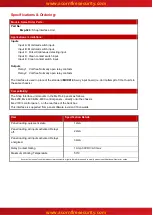
Specifications & Ordering: 

Models, Sales Order Parts: 

Part No: 

Mxp-029 : 

Shop Interface Unit 

Applications / Limitations: 

Inputs 

Input A : Monitored switch input. 
Input B : Monitored switch input. 
Input C : Pulse/Continuous detecting input. 
Input D : Clean contact switch input. 
Input E : Clean contact switch input. 
 

Outputs 

Relay 1 : Volt-free Normally open relay contacts 
Relay 2 : Volt-free Normally open relay contacts 


The Interface is used in place of the standard 

MXP-014 

8-

way input board (i.e. don’t attempt to fit both units to 

the same chassis). 


Compatibility: 

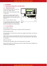
The Shop Interface unit mounts in the MxPro 4 panels as follows: 

Mx-4200, Mx-4400 & Mx-4800 control panels 

– directly onto the chassis.  

Mx-4100/L

 control panel 

– on the rear face of the back box. 

This interface is supported from panel software revision 016 onwards. 


Item 

Specification Details 

Panel loading, quiescent state 


12mA 

Panel loading, all inputs activated. Relays 
off. 


22mA 

Panel loading, all inputs activated. Relays 
energised. 


34mA 

Relay Contact Rating 


1 Amp 30V DC/AC max 

Maximum Working Temperature


50°C


As our policy is one of constant product improvement the right is therefore reserved to modify product specifications without prior notice 


www.acornfiresecurity.com

www.acornfiresecurity.com

Summary of Contents for MxPro 4

Page 1: ...t inputs with two of the inputs also supporting open circuit and short circuit fault monitoring on the external wiring A special input is also able to differentiate between an input that is pulsing AL...

Page 2: ...chassis Compatibility The Shop Interface unit mounts in the MxPro 4 panels as follows Mx 4200 Mx 4400 Mx 4800 control panels directly onto the chassis Mx 4100 L control panel on the rear face of the...

Page 3: ...Mounting the Card 4 1 1 2 Internal Wiring 4 1 2 INSTALLING THE MXP 029 IN THE MX 4200 MX 4400 MX 4800 5 1 3 MOUNTING THE CARD 5 1 4 INTERNAL WIRING 5 1 5 EXTERNAL WIRING 6 2 CONFIGURATION 7 2 1 ALERT...

Page 4: ...tion if the Mxp 014 8 Way Input Card Mxp 007 2 Way Relay card is already installed 1 1 2 Internal Wiring 1 4 way Ribbon Cable 1 Connect between PL2 and the 4 way O C Output connector on the base card...

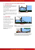
Page 5: ...PLY Base Card TB3 10 way Ribbon Cable 2 Shop Interface 4 way Ribbon Cable 1 Figure 3 Route the 10 way ribbon cable between the input card and the base card and then beneath the base card along the bot...

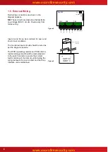
Page 6: ...s should be wired as per the diagram opposite The 470 operating resistor and 10k E O L resistor arrangement should be made adjacent to the switch contacts to ensure that correct fault monitoring of th...

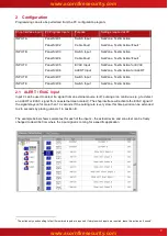
Page 7: ...ction 2 1 ALERT EVAC Input Input C can be used to detect if a signal from an external source is off pulsing or on continuous e g to detect an ALERT or EVAC signal from an external clean contact The sh...

Page 8: ...gram below shows these relays allocated to output Groups 190 191 respectively these group numbers are arbitrary any output group can be used For ease of recognition the text for each input has also be...

Page 9: ...USER NOTES www acornfiresecurity com www acornfiresecurity com...

Page 10: ...www acornfiresecurity com www acornfiresecurity com...

Reviews: