background image


2  Configuration 

Programming can also be performed from the PC configuration program. 


Shop Interface Input 

PC Program Inputs 

Purpose 

Settings required at PC 

INPUT A 

Panel S/W-1 

Panel S/W-2 

Switch Input 

Cable Fault 

Set Zone, Text & Action  

Set Zone, Text & Action=Fault 

1


INPUT B 

Panel S/W-3 

Panel S/W-4 

Switch Input 

Cable Fault 

Set Zone, Text & Action  

Set Zone, Text & Action=Fault 

1


INPUT C 

Panel S/W-5 

Panel S/W-6 

EVAC Input 

ALERT Input 

Set Zone, Text & Action for EVAC 

Set Zone, Text & Action for ALERT 

INPUT D 

Panel S/W-7 

Switch Input 

Set Zone, Text & Action 

INPUT E 

Panel S/W-8 

Switch Input 

Set Zone, Text & Action 

2.1  ALERT / EVAC Input 

Input C can be used to detect if a signal from an external source is off, pulsing or on continuous (e.g. to detect 
an ALERT or EVAC. signal from an external clean contact). The shop interface will activate the EVAC signal if 
the signal stays on for more than 1.3 seconds. If the pulsing rate is very slow, this time period can be extended 
to 2.6 seconds by placing jumper J1 in position B.


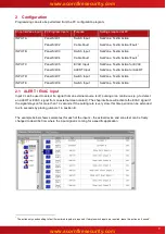
The example below shows sample text for each of the inputs 

– the actual device and zone text can be freely 

changed to describe from where the input signal is coming for a specific application. 


1


The action only needs setting to fault if monitored inputs are required. If simple switch inputs are required, leave this act

ion as “unused”.


www.acornfiresecurity.com

www.acornfiresecurity.com

Summary of Contents for MxPro 4

Page 1: ...t inputs with two of the inputs also supporting open circuit and short circuit fault monitoring on the external wiring A special input is also able to differentiate between an input that is pulsing AL...

Page 2: ...chassis Compatibility The Shop Interface unit mounts in the MxPro 4 panels as follows Mx 4200 Mx 4400 Mx 4800 control panels directly onto the chassis Mx 4100 L control panel on the rear face of the...

Page 3: ...Mounting the Card 4 1 1 2 Internal Wiring 4 1 2 INSTALLING THE MXP 029 IN THE MX 4200 MX 4400 MX 4800 5 1 3 MOUNTING THE CARD 5 1 4 INTERNAL WIRING 5 1 5 EXTERNAL WIRING 6 2 CONFIGURATION 7 2 1 ALERT...

Page 4: ...tion if the Mxp 014 8 Way Input Card Mxp 007 2 Way Relay card is already installed 1 1 2 Internal Wiring 1 4 way Ribbon Cable 1 Connect between PL2 and the 4 way O C Output connector on the base card...

Page 5: ...PLY Base Card TB3 10 way Ribbon Cable 2 Shop Interface 4 way Ribbon Cable 1 Figure 3 Route the 10 way ribbon cable between the input card and the base card and then beneath the base card along the bot...

Page 6: ...s should be wired as per the diagram opposite The 470 operating resistor and 10k E O L resistor arrangement should be made adjacent to the switch contacts to ensure that correct fault monitoring of th...

Page 7: ...ction 2 1 ALERT EVAC Input Input C can be used to detect if a signal from an external source is off pulsing or on continuous e g to detect an ALERT or EVAC signal from an external clean contact The sh...

Page 8: ...gram below shows these relays allocated to output Groups 190 191 respectively these group numbers are arbitrary any output group can be used For ease of recognition the text for each input has also be...

Page 9: ...USER NOTES www acornfiresecurity com www acornfiresecurity com...

Page 10: ...www acornfiresecurity com www acornfiresecurity com...

Reviews: