background image

BC-N4 Glycol Chiller

Page: 19

ADVANTAGE ENGINEERING, INC.

525 East Stop 18 Road Greenwood, Indiana 46142 

317-887-0729    Fax: 317-881-1277

Service Department Fax:  317-885-8683

Email: service@AdvantageEngineering.com

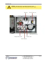
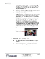
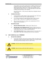
WARNING:  Check that all electrical connections are tight before starting.

Disconnect power before servicing. Follow all facility lock-out tag-out procedures.

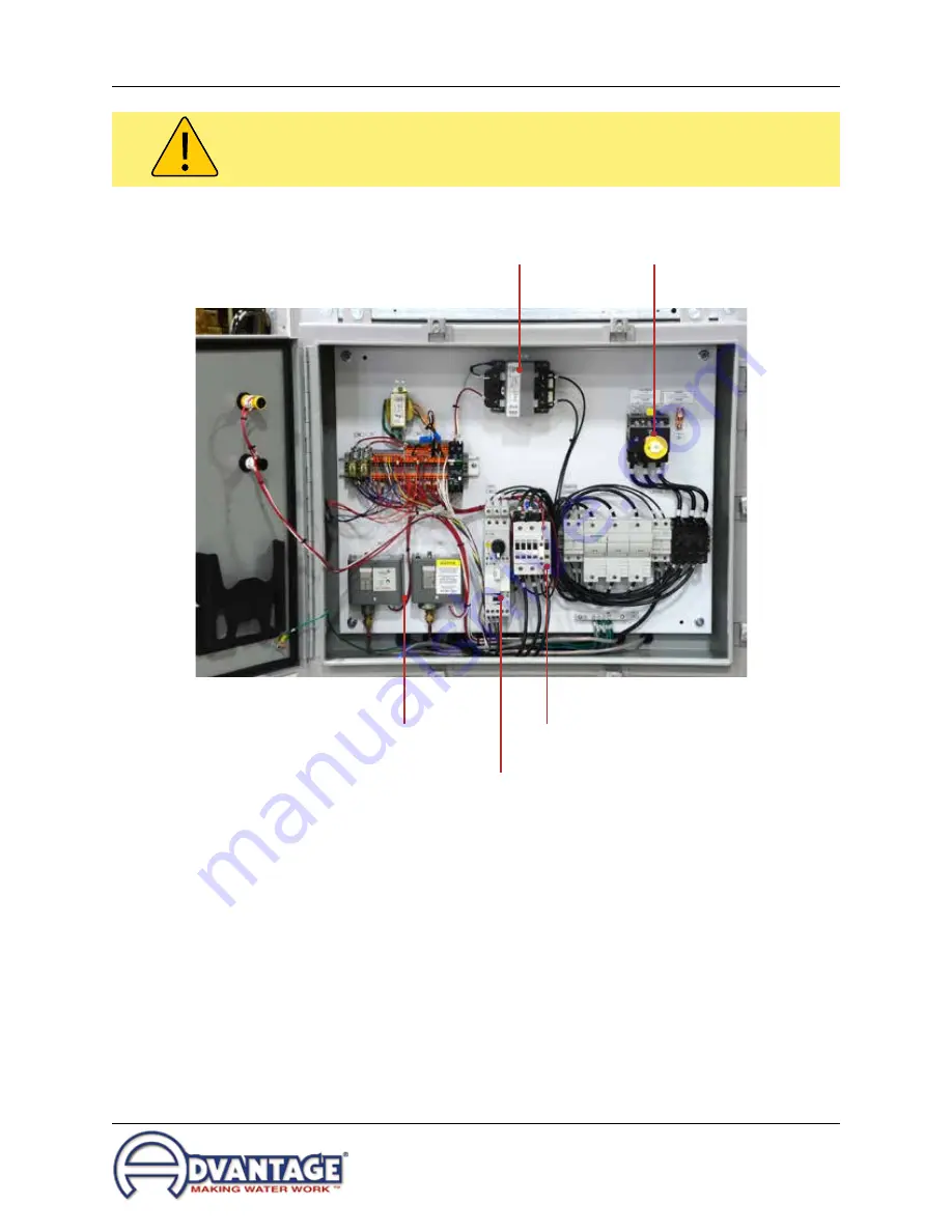
Refrigerant Pressure Limits

Transformer

Power Entry / Disconnect

Coolant Pump Stater

Compressor Starter

Typical electrical panel shown

Summary of Contents for BC-N4 Series

Page 1: ... models with M1 Instruments Scroll Compressors Model Serial Number Stop If running at a fluid temperature below 48 F or if the chiller will be installed in a climate where the ambient temperature may get below 40 F you must use a water and glycol mixture at a ratio that protects the fluid from freezing to approximately 25 F below the lowest expected set point temperature or the lowest expected amb...

Page 2: ......

Page 3: ... INSTALLATION OPERATION MAINTENANCE BC N4 Series G l y c o l C h i l l e r ADVANTAGE ENGINEERING INC 525 East Stop 18 Road Greenwood IN 46142 317 887 0729 fax 317 881 1277 Service Department fax 317 885 8683 Website www AdvantageEngineering com E mail service AdvantageEngineering com ...

Page 4: ... Start up operations procedure 22 3 3 Instrument operation 28 3 4 Shut down procedure 32 4 0 TROUBLESHOOTING 33 4 1 Unit Will Not Start 34 4 2 Compressor Hums But Will Not Start 34 4 3 Shuts Off On High Pressure 34 4 4 Shuts Off On Low Pressure 35 4 5 Compressor Shuts Off On Internal Overload 36 4 6 Low Or No Process Pressure Or Water Flow 36 4 7 Cooling Capacity Inadequate 37 4 8 Sensor 37 4 9 Co...

Page 5: ... Fax 317 881 1277 Service Department Fax 317 885 8683 Email service AdvantageEngineering com 7 0 RELATED DRAWINGS 55 7 1 Mechanical Schematic Air Cooled 25 1 5 Tons 56 8 0 APPENDIX 57 8 1 Operations below 48 F fluid or 38 F ambient 58 8 2 Inhibited propylene glycol 60 8 3 Refrigerant pressure temperature chart 61 ...

Page 6: ...Page 6 THIS PAGE INTENTIONALLY BLANK ...

Page 7: ...eenwood Indiana 46142 317 887 0729 Fax 317 881 1277 Service Department Fax 317 885 8683 Email service AdvantageEngineering com 1 0 GENERAL 1 1 Introduction 1 2 Safety 1 3 Receiving Instructions 1 4 Efficiency 1 5 Clean Air Act 1 6 Miscellaneous 1 7 Water Treatment 1 8 Components ...

Page 8: ...wever a system failure will release it Refrigerant gas can cause toxic fumes if exposed to fire Install this unit in a well ventilated area away from open flames Failure to follow these instructions may result in a hazardous condition Recover refrigerant to relieve pressure before opening the system See nameplate for refrigerant type Do not use non approved refrigerants or refrigerant substitutes ...

Page 9: ...s in literature and on tags stickers and labels located on the equipment Wear work gloves and safety glasses WARNING This equipment contains hazardous voltages that can cause severe injury or death Disconnect and lock out incoming power before installing or servicing the equipment WARNING This equipment contains refrigerant under pressure Accidental release of refrigerant under pressure can cause ...

Page 10: ...be followed The Manufacturer accepts no responsibility for inefficient operation or damage caused by foreign materials or failure to use adequate water treatment 1 5 CLEAN AIR ACT A Units manufactured after January 1 2010 may contain refrigerant HFC 410A HFC 407C HFC 404A or HFC 134A Most units manufactured prior to January 1 2010 contain refrigerant HCFC 22 B It is unlawful for any person in the ...

Page 11: ...that the services of a qualified water treatment specialist be engaged to determine what water treatment is required C Advantage assumes no responsibility for equipment failures which result from untreated or improperly treated water D Do not use deionized water in this unit Some customized units may be compatible with deionized water Consult the factory before using deionized water 1 7 COMPONENTS...

Page 12: ... 0729 Fax 317 881 1277 Service Department Fax 317 885 8683 Email service AdvantageEngineering com Protective Fan Shroud Air Cooled Condenser Process Connections Scroll Compressor Filer Drier Expansion Refrigerant Sight Glass Coolant Pump Remote Instrument Electrical Cabinet Reservoir Pressure Gauges Fan Motor ...

Page 13: ...a 46142 317 887 0729 Fax 317 881 1277 Service Department Fax 317 885 8683 Email service AdvantageEngineering com 2 0 INSTALLATION 2 1 General 2 2 Unit Location 2 3 To and From Process Connections 2 4 Make Up Water Supply Connection 2 5 Air Cooled Condenser Installation 2 6 Electrical Connection ...

Page 14: ...door or outdoor use 2 For most efficient operation locate the chiller in a level clean dry and well ventilated environment 3 The unit has an air cooled refrigerant condenser A motor driven fan generates air flow through the condenser to remove heat from the refrigerant system The air cooled condenser on the unit will discharge approximately 15 000 BTU s per hour for every 12 000 Btu hr of process ...

Page 15: ... or hose If using flexible hose avoid tight twists or curls and excessive lengths E Valves and filters may be installed in the process water piping to facilitate service and maintenance provided that such devices maintain the full inside diameter of the process connection If installed all such devices must be open and clean during unit operation 2 4 Make up WATER SUPPLY CONNECTION not equipped on ...

Page 16: ...be ducted on motor mounted fan models C A free air space of at least two 2 feet is required at the condenser intake and six 6 feet at the condenser discharge to allow for proper air flow D At full load the chiller will discharge approximately 15 000 BTU s per hour per ton of cooling The air cooled condenser on the unit will discharge approximately 15 000 BTU s per hour for every 12 000 Btu hr of p...

Page 17: ...sed disconnect switch There is no power entry hole into the electrical cabinet This allows the matching of the entry hole size and location to the customer supplied fittings 5 A unit specific electrical drawing is shipped with the unit 6 Voltage supplies must be within 10 of the name plate voltage and must be within 2 from leg to leg Extreme voltage imbalance or using the wrong voltage can damage ...

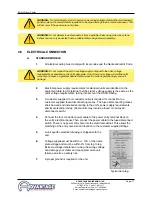
Page 18: ...ransformer A control circuit fuse is provided C GENERAL 1 Make certain all ground connections to the unit are properly affixed 2 Make certain power conductor disconnecting means and fusing are properly sized according to the unit s power supply requirements 3 Follow all local and national codes 4 Make certain that all owner and factory wire connections are tight before applying power to the unit W...

Page 19: ...ment Fax 317 885 8683 Email service AdvantageEngineering com WARNING Check that all electrical connections are tight before starting Disconnect power before servicing Follow all facility lock out tag out procedures Refrigerant Pressure Limits Transformer Power Entry Disconnect Coolant Pump Stater Compressor Starter Typical electrical panel shown ...

Page 20: ...Page 20 THIS PAGE INTENTIONALLY BLANK ...

Page 21: ...ING INC 525 East Stop 18 Road Greenwood Indiana 46142 317 887 0729 Fax 317 881 1277 Service Department Fax 317 885 8683 Email service AdvantageEngineering com 3 0 OPERATIONS 3 1 General 3 2 Start Up Operations Procedure 3 3 Instrument 3 4 Shut Down ...

Page 22: ...ater to fill the unit For operating temperatures below 48 F a water and propylene glycol mixtures must be used An inhibited propylene glycol can be used for operating temperatures above 48 F if desired to prevent corrosion and scaling Use the minimum ratio that is recommended by the glycol manufacturer See section 8 of this manual for more information 2 The unit has an internal reservoir which mus...

Page 23: ... panels to access the reservoir Add fluid directly to the reservoir When the pump is first started as process lines are filled and air is purged additional fluid may be required to restore the reservoir to the correct level Verify reservoir level via the coolant sight glass 6 Do not use deionized water in this unit unless your unit was specifically designed for use with deionized water Consult fac...

Page 24: ...r The operator must identify the motor shaft inside the electric motor housing The motor shaft can be seen through the vent slots in the motor housing or by removing the shaft cover d Toggle the illuminated ON OFF SWITCH This will quickly cycle the pump motor on and then off e Observe the motor shaft When the ON OFF SWITCH is on the motor shaft will rotate When switched off the shaft will slowly c...

Page 25: ... rate through the process is determined by the pressure losses in the process loop Generally higher flow rates result in turbulent flow achieving maximum temperature control and lower maintenance Since the evaporator in most liquid chillers is flow sensitive the efficiency of operation is directly related to the flow of liquid b Maximum chiller efficiency is obtained at approximately 2 4 gpm per t...

Page 26: ...reading is in the normal operating range for the refrigerant type used in the chiller For Automatic Low Flow Bypass Valves A T handle or adjusting stem is located on the top of the valve Turning the T handle or adjusting stem in the clockwise direction puts more pressure on the valve s spring reducing bypass flow Turning the T handle or adjusting stem counter clockwise puts less pressure on the sp...

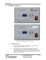
Page 27: ...d adequate water supply pressure are supplied to the unit it is possible to start the unit 2 Upon power up the instrument displays ChF indicating that the unit is in Fahrenheit temperature mode or ChC indicating that it is in Celsius mode The control then shows the current setpoint for approximately 2 seconds before reverting to the To Process temperature When power is supplied to the unit the ON ...

Page 28: ...ntrol will begin temperature control operations 2 To select setpoint temperature press and hold the UP ARROW or DOWN ARROW keys until the desired set point temperature is displayed in the TEMPERATURE WINDOW The default range for the setpoint temperature is 48 70 F or 9 21 C 3 The setpoint temperature can be displayed by pressing the UP ARROW or DOWN ARROW keys The setpoint temperature will be disp...

Page 29: ...or 9 C If the jumper is in position 2 closest to the SPL label the user is allowed to reduce the setpoint to 10 F or 11 C 4 TEMPERATURE DISPLAY JUMPER If this jumper is in the F position the To Process and Setpoint temperatures are displayed in Fahrenheit If the jumper is in the C position the To Process and Setpoint temperatures are displayed in Celsius 5 Probe Calibration This pot CALPOT 1 is us...

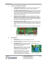
Page 30: ...ways displayed unless a button has been pressed If there is a probe error the display will show three dashes 3 When the water temperature in the chiller is above approximately 100 F the display will show three dashes F PRESSURE GAUGES 1 PROCESS PRESSURE GAUGE Indicates process pump pressure 2 REFRIGERANT HEAD PRESSURE GAUGE Indicates refrigerant pressure on the discharge side of the compressor The...

Page 31: ... Service Department Fax 317 885 8683 Email service AdvantageEngineering com B UNIT SHUT DOWN 1 To shut down the unit without disconnecting from the process a Move the ON OFF switch to the off position 2 To shut down the unit and disconnect from the process a Move the ON OFF switch to the off position b Disconnect all process lines ...

Page 32: ...Page 32 THIS PAGE INTENTIONALLY BLANK ...

Page 33: ...885 8683 Email service AdvantageEngineering com 4 0 TROUBLESHOOTING 4 1 Unit Will Not Start 4 2 Compressor Hums But Will Not Start 4 3 Shuts Off On High Pressure 4 4 Shuts Off On Low Pressure 4 5 Compressor Shuts Off On Internal Overload 4 6 Low Or No Process Pressure Or Water Flow 4 7 Cooling Capacity Inadequate 4 8 Sensor 4 9 Pumps 4 10 Chiller Controller ...

Page 34: ...n power supply coming into the plant call the local power company D Loose terminals Power off and follow all company lock out tag out procedure before tightening terminals 4 3 SHUTS OFF ON HIGH PRESSURE LIMIT Note Units may be equipped with either an adjustable or non adjustable fixed high pressure switch If the refrigerant pressure exceeds the setting of the adjustable switch it must be manually ...

Page 35: ...uding freezing and rupture of the chiller evaporator The low pressure switch is set to cut out at 32 F and cut in at 36 F 39 F If a low pressure condition exists for more than five seconds the compressor will stop and a L P fault will appear in the display window After the refrigerant pressure rises above the cut in pressure a three minute time delay will occur before the compressor restarts This ...

Page 36: ...place if defective 4 6 LOW OR NO PROCESS PRESSURE OR WATER FLOW A Valves Check if water valves are open B Pump Check pump for correct rotation Check pump suction for restriction Replace motor if defective C Filters Check filter in the chilled water circuit and clean if necessary D Pressure switch or flow switch Readjust or replace if defective E Fuses and wiring Have electrician check the fuses an...

Page 37: ...control instrument is used for all normal set ups diagnostics temperature readout and operational information It contains the software and electronic components which operate the control instrument B The control instrument is not field repairable It can be easily removed and replaced or repaired if a problem occurs C All control instruments used in Advantage water chillers are covered by the machi...

Page 38: ...prepaid For a nominal fee contact factory for current fees your instrument will be repaired and returned c Purchase a new instrument and repair the old one as a back up 3 Do not disassemble the instrument F Other Information 1 Repair Warranty 1 year 2 Ship to Advantage Engineering 525 East Stop 18 Road Greenwood IN 46143 Attention Repairs 317 887 0729 3 Include in box part purchase order contact n...

Page 39: ...77 Service Department Fax 317 885 8683 Email service AdvantageEngineering com 5 0 MAINTENANCE 5 1 Warranty Service Procedure 5 2 Periodic Preventative Maintenance 5 3 Special Maintenance 5 4 Solenoid Valve Service 5 5 Pump Seal Service 5 6 Checking The Refrigerant Charge 5 7 Proper Cleaning Procedure For Brazed Plate Evaporator ...

Page 40: ...d recommend available service contractors C It is of the utmost importance that you provide the correct model number and serial number of the machine in question This will allow the Service Department to obtain the correct manufacturing records which will help to properly troubleshoot the problem and obtain the proper replacement parts when they are required This information is stamped on the data...

Page 41: ...142 317 887 0729 Fax 317 881 1277 Service Department Fax 317 885 8683 Email service AdvantageEngineering com 1 Addition of compressor oil 2 Addition of refrigerant 3 Repair of a refrigerant leak 4 Adjustment of super heat 5 Changing of filter drier or drier core 6 Repair of a refrigeration solenoid ...

Page 42: ...d D Make up solenoid valve service 1 The make up solenoid valve may require service for a failed coil or more often it will not fully close because debris from poor make up water quality is in the valve mechanism 2 To replace the coil disengage power from the unit following all lock out tag out procedures Remove the wires from the failed coil and remove the coil from the valve stem Install the new...

Page 43: ...Service Department Fax 317 885 8683 Email service AdvantageEngineering com Coil and solenoid base sub assembly Body Gasket Valve body Core Core spring Diaphragm spring Diaphragm assembly f Note the arrangement of the core spring and core assembly diaphragm spring and diaphragm assembly See diagram g Clean all components as required ...

Page 44: ...he pump motor by opening or removing any cover panels as necessary figure 5 5B 4 Drain machine The machine can be drained by using the drain valve located on the pump case Drain fluid into a suitable container for reuse or disposal according to manufacturer s instructions if a glycol solution is used 5 Locate and remove the three motor wire leads from the motor wiring terminals The operator should...

Page 45: ...quared and seated in cavity 13 Slide the rotating member onto lubricated pump shaft figure 5 5J The operator must be certain not to damage or tear rubber bellows assembly 14 Place the spring onto the rotating member 15 Align the impeller spring and rotating member before reinstalling the impeller figure 5 5K The operator must be certain the spring and rotating member are aligned before the impelle...

Page 46: ...ation technician 5 7 PROPER CLEANING PROCEDURE FOR BRAZED PLATE EVAPORATORS A The brazed plate evaporator is made of stamped stainless steel plates furnace brazed together with copper based joints The complex geometry of the flow passages promotes turbulent flow which gives high efficiency and reduces fouling by mineral deposits Large solids such as plastic pellets or chunks of mineral deposits wi...

Page 47: ...ir tank Dispose of all back flush fluid according to local codes 4 The cleaning fluid source should have at least 20 psi available If acid cleaning follow the instructions supplied with the acid solution carefully 5 When the procedure is complete reinstall all water lines to original factory orientation Restart the unit and check for proper operation 6 Note This procedure is not normal maintenance...

Page 48: ...Page 48 THIS PAGE INTENTIONALLY BLANK ...

Page 49: ...GE ENGINEERING INC 525 East Stop 18 Road Greenwood Indiana 46142 317 887 0729 Fax 317 881 1277 Service Department Fax 317 885 8683 Email service AdvantageEngineering com 6 0 COMPONENTS 6 1 Water System 6 2 Refrigeration System 6 3 Options ...

Page 50: ...l blower C FILTER DRIER The filter drier removes contaminants and moisture from the liquid refrigerant D LIQUID LINE SOLENOID VALVE Controlled by the instrument this valve closes when the compressor cycles off to prevent refrigerant liquid from migrating to the evaporator The valve opens when the compressor cycles on E REFRIGERANT SIGHT GLASS The refrigerant sight glass indicates refrigerant charg...

Page 51: ...E SWITCH The high and low pressure switches protect the refrigeration system from usage operating conditions Units may be equipped with either an adjustable or non adjustable fixed high and low pressure switches The high pressure switch is factory set and protects the refrigeration components and personnel from potential damage and injury from excessive pressure The high pressure safety must not b...

Page 52: ...talled on the to and from process lines at the exit of the chiller These valves can be used to adjust the process flow rate and to shut off the flow rate to isolate the chiller D E STOP BUTTON The Emergency stop button is a mushroom type button which will shut down all chiller operations when engaged E NON FUSED OR FUSED DISCONNECT SWITCH On board disconnect switch provides a convenient location f...

Page 53: ...277 Service Department Fax 317 885 8683 Email service AdvantageEngineering com process acts as the chiller reservoir and gravity returns water to the pump suction System water make up and level control is accomplished externally at the process since the chiller contains no reservoir Typical Alarm Beacon Typical Condenser Screen ...

Page 54: ...Page 54 THIS PAGE INTENTIONALLY BLANK ...

Page 55: ...ADVANTAGE ENGINEERING INC 525 East Stop 18 Road Greenwood Indiana 46142 317 887 0729 Fax 317 881 1277 Service Department Fax 317 885 8683 Email service AdvantageEngineering com 7 0 RELATED DRAWINGS 7 1 Typical Mechanical Schematic ...

Page 56: ...an Hot Gas Bypass Valve not applicable with digital compressors Expansion Valve Evaporator High Flow Pump Glycol Reservoir Compressor To Process Pressure Gauge To Process Sensor Probe Low Flow Bypass From Process To Process Optional Low Ambient Control System Provides efficient operation in ambient conditions to 20 F Required when ambient condition may be below 50 F Includes flooding control valve...

Page 57: ... East Stop 18 Road Greenwood Indiana 46142 317 887 0729 Fax 317 881 1277 Service Department Fax 317 885 8683 Email service AdvantageEngineering com 8 0 APPENDIX 8 1 Operations Below 48 F 8 2 Inhibited Propylene Glycol 8 3 Refrigerant Pressure Temperature Chart ...

Page 58: ...ce the protective devices may be adjusted and the control instrument can be unlocked to allow operation below 48 F E If your unit is equipped with an adjustable low pressure switch adjust the low pressure switch according to the specifications in the chart on the next page Never lower the cut out setting on the adjustable low pressure switch without adding glycol to the circulating system Evaporat...

Page 59: ... Out 52 28 16 Cut In 58 34 22 R407C Refrigerant Low Pressure Switch Cut Out Cut In Settings High Pressure Cut Out maximum the user IS NOT ALLOWED to reduce the setpoint below 48 F or 9 C If the jumper is in position 2 closest to the SPL label the user is allowed to reduce the setpoint to 10 F or 11 C To operate below 48 F leaving fluid temperature the jumper will need to be in position 2 See Figur...

Page 60: ...n steel it is 4 5 times faster D MAINTENANCE RESPONSIBILITY A refractometer shown below should be used on a regular basis to determine the mixture strength according to freeze point The freeze point temperature should be 25 F below the lowest required setpoint see chart or the lowest expected ambient temperature whichever is lower Water may evaporate from the mixture and if you continue to add a p...

Page 61: ...ge 61 ADVANTAGE ENGINEERING INC 525 East Stop 18 Road Greenwood Indiana 46142 317 887 0729 Fax 317 881 1277 Service Department Fax 317 885 8683 Email service AdvantageEngineering com 8 3 REFRIGERANT PRESSURE TEMPERATURE CHART ...

Page 62: ...Page 62 THIS PAGE INTENTIONALLY BLANK ...

Page 63: ...END 2016 ADVANTAGE ENGINEERING INC RE 09 27 2016 ...

Page 64: ......

Reviews: