background image

3

CONTROLS

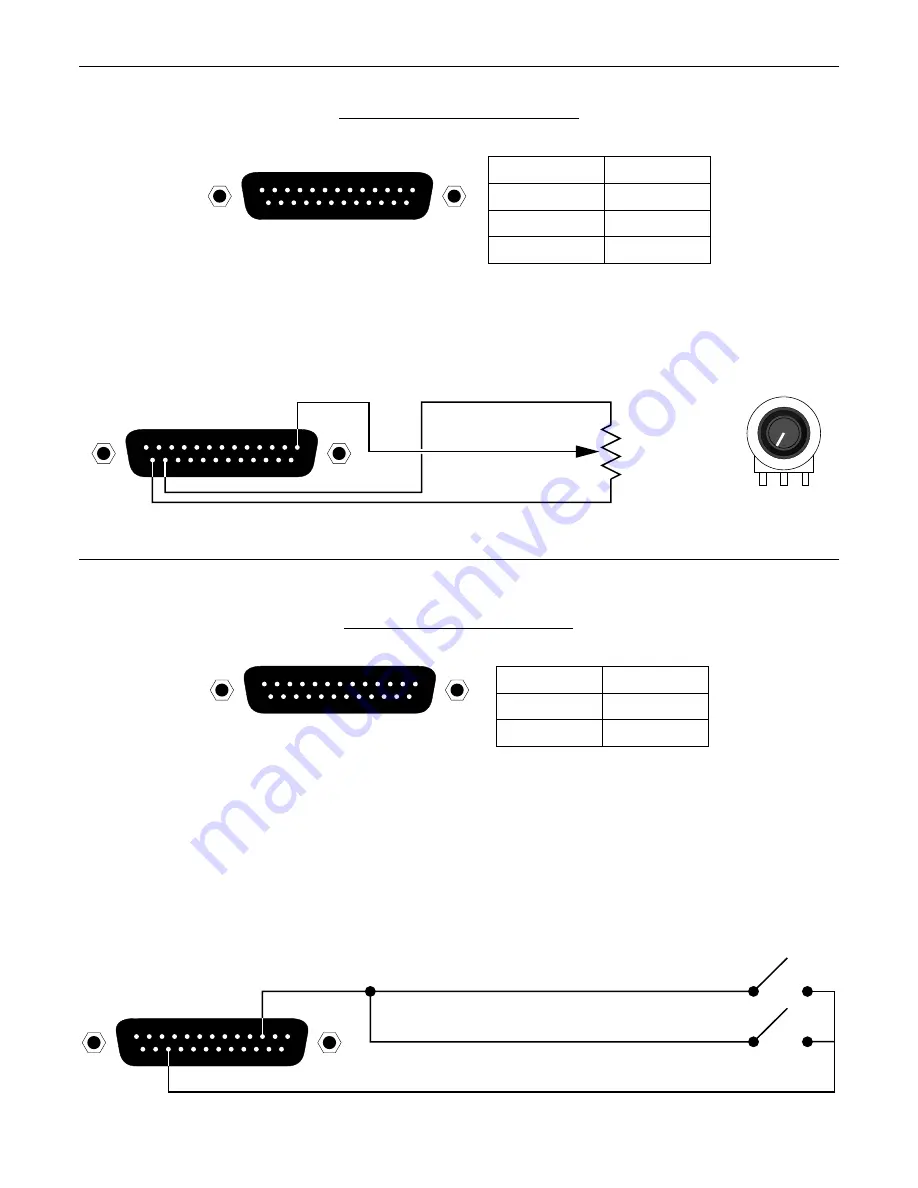
REMOTE CONTROL / POTENTIOMETERS

remote control

pin numbers

pots #1~23

+5 Volts

pin #1~23

pin #24

ground

pin #25

remote control

13

1

25

14

Rotary or slide potentiometers may be used with the RCU.  Potentiometers should be between 5k ohms and 50k ohms in value, with a
linear taper.  Potentiometers are wired to the RCU Remote Control port with the ‘high’ side of the potentiometer to +5 Volts (pin 24), the
‘low’ side of the potentiometer to ground (pin 25), & the ‘wiper’ of the potentiometer to the desired control terminal (pins 1~23).

13

1

25

14

potentiometer wiring

5k

Ω∼

50k

linear taper

gnd pot +5V

low (ccw)

wiper

pot #1

high (cw)

ground

+5 Volts

cw

ccw

w

LOGIC INPUTS / CONTACT-CLOSURES

logic inputs

pin numbers

logic #1~24

ground

pin #1~24

pin #25

logic inputs

13

1

25

14

When nothing is connected to a Logic Input, an internal pull-up resistor keeps it at a ‘high’ idle state (+5.0 VDC).  The Logic Input is
activated when its input goes ‘low’ (less than +0.8 VDC), and is de-activated when its input goes ‘high’ (greater than +2.4 VDC).  A Logic
Input is controlled in one of three ways:  1)  Use a switch, relay, or other contact-closure (such as from a third-party controller) to short the
Logic Input to ground.  2)  Use an NPN style ‘open-collector’ logic output from an external to short the Logic Input to ground.  3)  Use an
active TTL output driver circuit (such as from a third-party controller) to actively drive the Logic Input to a ‘high’ or ‘low’ state.  Multiple
contact-closures or ‘open-collector’ logic outputs may be wired in parallel to a single Logic Input (see diagram below). Logic Outputs and
contact-closures should be rated for at least 5 Volts / 1mA operation.  Low-current / dry-contact closures are recommended for reliability.
Active output driver circuits should not exceed a signal range of 0~5 Volts DC, and should have a minimum pulse width of 100 milli-
seconds.  Logic Input impedances are approximately 10k ohms.

13

1

25

14

multiple switches to single Logic Input

Summary of Contents for RCU

Page 1: ...ADVANTAGE RCU Remote Control Unit Operation Manual 9 2 99 Biamp Systems 10074 S W Arctic Drive Beaverton Oregon 97005 U S A 503 641 7287 http www biamp com an affiliate of Rauland Borg Corp ...

Page 2: ...blank ...

Page 3: ...on recall preset functions within a system having multiple ADVANTAGE products The RCU carries a five year warranty RCU features include RS 232 serial link ports for communication with products remote control port accepts up to 23 potentiometers logic inputs port accepts up to 24 contact closures programming software assigns functions to controls potentiometers provide various level control functio...

Page 4: ...utput Pin 3 Receive Data RxD input Pin 4 not used Pin 5 Ground Pin 6 Data Set Ready DSR output Pin 7 not used Pin 8 Clear To Send CTS output Pin 9 not used NOTE The Link Port also transmits commands assigned to external potentiometer contact closures see Remote Control Logic Inputs below Link Switch The Link Switch is used when connecting multiple devices in a Link Port to Serial Port configuratio...

Page 5: ...DC The Logic Input is activated when its input goes low less than 0 8 VDC and is de activated when its input goes high greater than 2 4 VDC A Logic Input is controlled in one of three ways 1 Use a switch relay or other contact closure such as from a third party controller to short the Logic Input to ground 2 Use an NPN style open collector logic output from an external to short the Logic Input to ...

Page 6: ...een The Main screen appears whenever an RCU file is opened Pot Definition Logic Input Definition Configuration Options screens are then available from the Configure RCU menu The File menu provides functions such as open close save etc The Settings menu recalls the Comm Port Configuration screen The Window menu arranges the active product screens The Help menu explains the available adjustments To ...

Page 7: ...disabled the LED indicator is grayed out slightly and a small X appears in the LED The LED indicator is updated whenever the logic input status is changed even if the logic input is disabled When the LED indicator is on red the switch contact is closed the logic input is shorted to ground through the contact closure When the LED indicator is off the switch contact is open Each logic input may be p...

Page 8: ... Muting checkbox appears With these models if you wish to use a pot as a volume control AND use a logic input to perform muting functions for the pot you should select the Use Logic Input for Muting checkbox and an appropriate logic input definition will automatically be created for you This links the operation of the logic input and the pot allowing for cooperative control NOTE Use Logic Input fo...

Page 9: ...ing the Configuration Options Screen the six highest logic inputs 19 through 24 may be programmed to operate in binary mode When in binary mode a logic input definition may be created for each of the 64 possible binary on off combinations of logic inputs 19 through 24 Logic inputs may also be programmed to enable disable other logic inputs or pots or to transmit a user defined ASCII character stri...

Page 10: ...reen for that RCU Each RCU may be assigned a device number from 0 to 63 This allows multiple RCUs or other ADVANTAGE programmable products to be individually controlled when linked together Unique device numbers must be assigned to each device before the devices are linked together The last six logic inputs logic inputs 19 through 24 may be configured to operate in binary mode In this mode wheneve...

Page 11: ...MP SYSTEMS Portland Oregon an affiliate of Rauland Borg Corp RCU 2 50 1 COMPACT DIGITAL AUDIO microphones channels 1 8 Logic Input 17 defined to select between enable disable pots 1 22 manual mode logic inputs 1 16 auto mode presets Logic Inputs 1 16 defined to recall VRAM presets 1 16 Pots 1 22 defined to adjust all VRAM input output levels CD player aux 1 cassette aux 2 Main Output Aux Output VR...

Page 12: ...unt control panel corresponds to one character in the standard ASCII character set The character equivalents are summarized in the following table This table includes all forty possible buttons their button numbers and their ASCII code equivalents Their button definitions are defined during programming of the product to be controlled button 01 B programmable by product button 15 P programmable by ...

Page 13: ...l and the PC should get AC power from the same source as the RCU and any other audio equipment which is connected to the RCU Since most lap top computers are isolated from earth ground this should rarely pose a problem Serial Port Data Communications Parameters The RCU communicates through the Serial Port at the factory selected rate of 9600 bits per second with 8 data bits 1 stop bit and no parit...

Page 14: ... fans electrolytic capacitors and the normal wear and tear of appearance items such as paint knobs handles and covers are not covered under this warranty 4 BIAMP SYSTEMS SHALL NOT IN ANY EVENT BE LIABLE FOR SPECIAL INCIDENTAL OR CONSEQUENTIAL DAMAGES INCLUDING LOST PROFITS LOSS OF USE PROPERTY DAMAGE INJURY TO GOODWILL OR OTHER ECONOMIC LOSS OF ANY SORT EXCEPT AS EXPRESSLY PROVIDED HEREIN BIAMP SY...

Page 15: ......

Page 16: ......

Page 17: ......

Page 18: ......

Reviews: