background image

6

SETUP

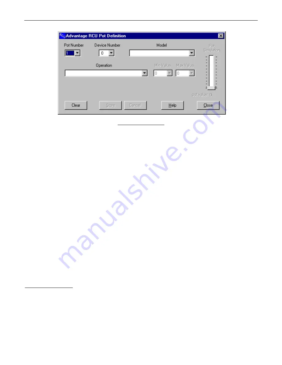
POT DEFINITION SCREEN

Up to 23 potentiometers may be connected to the Remote Control input port of the RCU.  Each pot may be programmed to perform a
specific control function for a specific product.  The programming process is performed using the Pot Definition Screen.  Each product that
is linked to the RCU must have a unique device number.  When creating a pot definition, you must specify the device number of the
product which that pot will be controlling.  You must also specify the model of the product (VRAM, MSP22e, etc.).  Once you have specified
the model, a list of available operations appears in the “Operation” list box.  The list of operations changes depending upon which model is
selected.  Most operations also allow you to specify a minimum value and a maximum value for the pot.  If you do not override the default
values shown, the entire range of pot travel will correspond directly to the entire volume range that is possible for the specified operation.
By specifying a Min Value and/or a Max Value, you may restrict the range of volume levels for the pot.  For example, each volume control
on an VRAM has 32 settings (or ‘steps’), ranging from a minimum value of 0 to a maximum value of 31.  If you set Min Value to 3 and Max
Value to 28, then the fully counter-clockwise position of the pot will correspond to volume step 3 and the fully clockwise position of the pot
will correspond to volume step 28.  A “Pot Simulation” fader appears on the Pot Definition Screen.  This fader provides a convenient
method to test the pot definition as it is being created.  Using the mouse to move the fader knob simulates the movement of the actual
potentiometer which is being defined.  During an on-line session, moving the Pot Simulation fader knob will cause BiampWin to transmit
the appropriate character string commands to the specified product.  

NOTE:

  RS-232 level commands from other sources, including the

Pot Simulation fader, may conflict with actual pot settings.  However, these conflicts are resolved as soon as the pot is again manipulated.

If the specified model is either a VRAM/VRAMeq or an SPM522D, then a “Use Logic Input for Muting” checkbox appears.  With these
models, if you wish to use a pot as a volume control AND use a logic input to perform muting functions for the pot, you should select the
“Use Logic Input for Muting” checkbox and an appropriate logic input definition will automatically be created for you.  This links the
operation of the logic input and the pot, allowing for cooperative control.  

NOTE:

  “Use Logic Input for Muting” is defined to mute when a

switch closes, and un-mute when the switch opens.  Therefore, a ‘latching’ switch will maintain the selected muting status (muted or un-
muted), whereas a ‘momentary’ switch will temporarily mute (only while the switch is held closed).

  Other forms of muting are available,

which behave differently when used in conjunction with a pot (see Logic Input Definition Screen on next page).  However, these forms of
muting may cause conflicts, such as un-muting when the pot is manipulated, and un-muting to levels established by means other than the
pot (RS-232 commands, Pot Simulation fader, product software, etc.).  In some cases, these forms of muting may actually be considered
desirable.  When a definition has been established for a particular pot, an icon and device number will appear above the fader on the Main
Screen.  The icon and device number indicate which device the pot is programmed to control.  When the mouse pointer is positioned over
the fader, a pop-up ‘hint’ appears which provides a detailed description of the function which the pot is programmed to perform.

Connecting Pots to the RCU:  The RCU is designed to be used with linear taper pots.  The resistance value of the pots can be as low as
5K ohms or as high as 50K ohms.  Pins 1 through 23 of the “Remote Control” connector on the RCU are for pot inputs.  Pin 24 is a
reference voltage output (which is approxi5 volts DC), and pin 25 is ground.  The ‘high’ (clockwise) side of all pots should be
connected to the reference voltage output on pin 24 of the remote control connector.  The ‘low’ (counter-clockwise) side of all pots should
be connected to ground on pin 25 of the remote control connector.  The wiper of each pot should be connected to the pin corresponding to
the pot number (1 through 23).  In some cases, the wiper could be connected to more than one pin if you want to control more than one
volume level with the same pot (to simulate a ‘ganged’ pot).

Summary of Contents for RCU

Page 1: ...ADVANTAGE RCU Remote Control Unit Operation Manual 9 2 99 Biamp Systems 10074 S W Arctic Drive Beaverton Oregon 97005 U S A 503 641 7287 http www biamp com an affiliate of Rauland Borg Corp ...

Page 2: ...blank ...

Page 3: ...on recall preset functions within a system having multiple ADVANTAGE products The RCU carries a five year warranty RCU features include RS 232 serial link ports for communication with products remote control port accepts up to 23 potentiometers logic inputs port accepts up to 24 contact closures programming software assigns functions to controls potentiometers provide various level control functio...

Page 4: ...utput Pin 3 Receive Data RxD input Pin 4 not used Pin 5 Ground Pin 6 Data Set Ready DSR output Pin 7 not used Pin 8 Clear To Send CTS output Pin 9 not used NOTE The Link Port also transmits commands assigned to external potentiometer contact closures see Remote Control Logic Inputs below Link Switch The Link Switch is used when connecting multiple devices in a Link Port to Serial Port configuratio...

Page 5: ...DC The Logic Input is activated when its input goes low less than 0 8 VDC and is de activated when its input goes high greater than 2 4 VDC A Logic Input is controlled in one of three ways 1 Use a switch relay or other contact closure such as from a third party controller to short the Logic Input to ground 2 Use an NPN style open collector logic output from an external to short the Logic Input to ...

Page 6: ...een The Main screen appears whenever an RCU file is opened Pot Definition Logic Input Definition Configuration Options screens are then available from the Configure RCU menu The File menu provides functions such as open close save etc The Settings menu recalls the Comm Port Configuration screen The Window menu arranges the active product screens The Help menu explains the available adjustments To ...

Page 7: ...disabled the LED indicator is grayed out slightly and a small X appears in the LED The LED indicator is updated whenever the logic input status is changed even if the logic input is disabled When the LED indicator is on red the switch contact is closed the logic input is shorted to ground through the contact closure When the LED indicator is off the switch contact is open Each logic input may be p...

Page 8: ... Muting checkbox appears With these models if you wish to use a pot as a volume control AND use a logic input to perform muting functions for the pot you should select the Use Logic Input for Muting checkbox and an appropriate logic input definition will automatically be created for you This links the operation of the logic input and the pot allowing for cooperative control NOTE Use Logic Input fo...

Page 9: ...ing the Configuration Options Screen the six highest logic inputs 19 through 24 may be programmed to operate in binary mode When in binary mode a logic input definition may be created for each of the 64 possible binary on off combinations of logic inputs 19 through 24 Logic inputs may also be programmed to enable disable other logic inputs or pots or to transmit a user defined ASCII character stri...

Page 10: ...reen for that RCU Each RCU may be assigned a device number from 0 to 63 This allows multiple RCUs or other ADVANTAGE programmable products to be individually controlled when linked together Unique device numbers must be assigned to each device before the devices are linked together The last six logic inputs logic inputs 19 through 24 may be configured to operate in binary mode In this mode wheneve...

Page 11: ...MP SYSTEMS Portland Oregon an affiliate of Rauland Borg Corp RCU 2 50 1 COMPACT DIGITAL AUDIO microphones channels 1 8 Logic Input 17 defined to select between enable disable pots 1 22 manual mode logic inputs 1 16 auto mode presets Logic Inputs 1 16 defined to recall VRAM presets 1 16 Pots 1 22 defined to adjust all VRAM input output levels CD player aux 1 cassette aux 2 Main Output Aux Output VR...

Page 12: ...unt control panel corresponds to one character in the standard ASCII character set The character equivalents are summarized in the following table This table includes all forty possible buttons their button numbers and their ASCII code equivalents Their button definitions are defined during programming of the product to be controlled button 01 B programmable by product button 15 P programmable by ...

Page 13: ...l and the PC should get AC power from the same source as the RCU and any other audio equipment which is connected to the RCU Since most lap top computers are isolated from earth ground this should rarely pose a problem Serial Port Data Communications Parameters The RCU communicates through the Serial Port at the factory selected rate of 9600 bits per second with 8 data bits 1 stop bit and no parit...

Page 14: ... fans electrolytic capacitors and the normal wear and tear of appearance items such as paint knobs handles and covers are not covered under this warranty 4 BIAMP SYSTEMS SHALL NOT IN ANY EVENT BE LIABLE FOR SPECIAL INCIDENTAL OR CONSEQUENTIAL DAMAGES INCLUDING LOST PROFITS LOSS OF USE PROPERTY DAMAGE INJURY TO GOODWILL OR OTHER ECONOMIC LOSS OF ANY SORT EXCEPT AS EXPRESSLY PROVIDED HEREIN BIAMP SY...

Page 15: ......

Page 16: ......

Page 17: ......

Page 18: ......

Reviews: