AIIS-3411 User Manual
12
2.1.6
COM Connectors
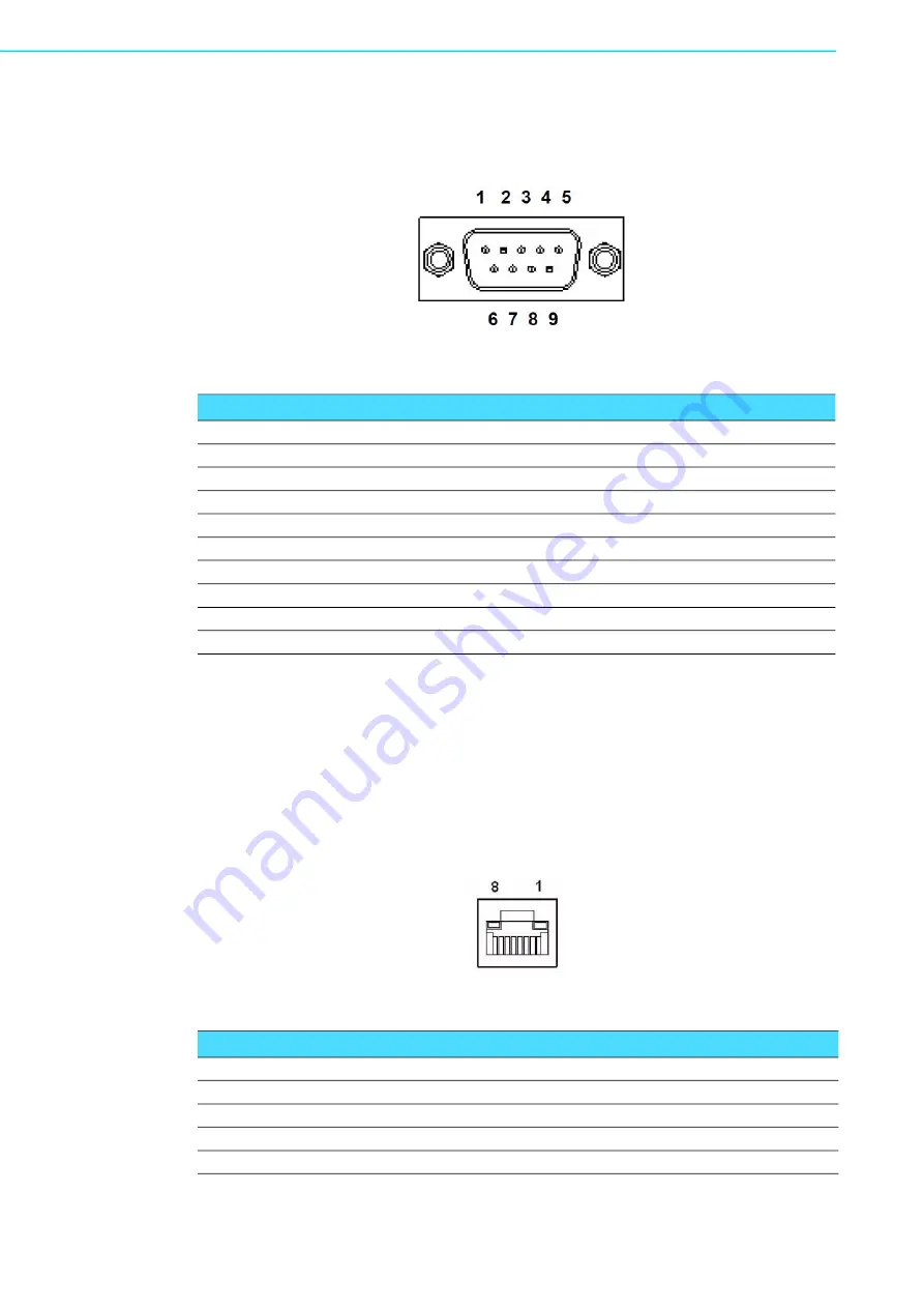
The AIIS-3411 provides 2 D-sub 9-pin connectors that are serial communication
interface ports. COM-1 & COM-2 support RS-232/422/485 mode by BIOS selection.
Figure 2.8 COM Connectors
2.1.7
Ethernet Connectors (LANs)
The AIIS-3411 provides six RJ45 connectors for Gigabit LAN interfaces; two of them
are equipped with Intel
®
i219LM, i210AT Ethernet Controllers, and four of them are
equipped with Intel
®
i210 Ethernet Controllers that are fully compliant with the IEEE
802.3af Power over Ethernet standard. The Ethernet ports provide standard RJ-45
jack connectors with LED indicators that show Active/Link status (Green LED) and
Speed status (Yellow LED).
Figure 2.9 Ethernet Connector
Table 2.7: Front 2-COM Pin Assignment
Pin
RS-232
RS-422
RS-485
1
DCD
TXD -
DATA -
2
SIN#
TXD +
DATA +
3
SOUT#
RXD +
NC
4
DTR
RXD -
NC
5
GND
GND
GND
6
DSR
NC
NC
7
RTS
NC
NC
8
CTS
NC
NC
9
RI
NC
NC
Table 2.8: Ethernet Connector Pin Assignment
Pin
Signal
Pin
Signal
1
MDI0 +
2
MDI0 -
3
MDI1 +
4
MDI1 -
5
MDI2 +
6
MDI2 -
7
MDI3 +
8
MDI3 -
Summary of Contents for AIIS-3411 Series
Page 1: ...User Manual AIIS 3411 Machine Vision System Computer ...
Page 8: ...AIIS 3411 User Manual viii ...
Page 12: ...AIIS 3411 User Manual xii ...
Page 36: ...AIIS 3411 User Manual 24 ...
Page 37: ...Chapter 3 3 AMI BIOS Setup ...
Page 48: ...AIIS 3411 User Manual 36 3 2 2 8 Super IO Configuration Figure 3 11 Super IO Configuration ...
Page 64: ...AIIS 3411 User Manual 52 ...
Page 65: ...Chapter 4 4 Software Installation This chapter introduces driver installation ...
Page 69: ...57 AIIS 3411 User Manual Chapter 4 Software Installation ...
Page 70: ...AIIS 3411 User Manual 58 ...
Page 71: ...Appendix A A Programming the Watchdog Timer ...
Page 79: ...Appendix B B 32 bit DIO Signal Connections ...
Page 82: ...AIIS 3411 User Manual 70 ...
Page 83: ...Appendix C C Exploded Diagram Parts List ...
Page 84: ...AIIS 3411 User Manual 72 C 1 Exploded Diagram Figure C 1 Exploded Diagram ...


