background image

GESTEK


Lab


Report No.: 0609083 Rev. 1

N0 3, Pau-Tou-Tsuo Valley, Chia-Pau Tsuen, Lin Kou Hsiang, Taipei County, Taiwan, R.O.C.      Tel:886-2-2603-5321    Fax:886-2-2603-5325


Accredited Lab. Of BSMI, NEMKO, NVLAP  

Page     18   of  59 


Listed Lab. of AUSTEL, Commerce, FCC, VCCI 

NVLAP Lab Code:200085-0 


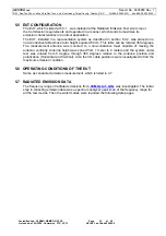
5.5 EUT CONFIGURATION  

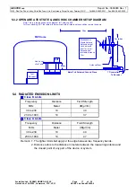
The EUT, which is listed at 5.3.1. , was installed at the Radiated Emission Test site to meet 
the Commission requirements and operated in a manner, which tends to maximize its 
emission characteristics in a normal application. 
The EUT, installed in a representative system as described in section 5.3.2, was placed on a 
non-conductive table whose total height equaled 80 cm. This table can be rotated 360 degrees. 
The measurement antenna was mounted to a non-conductive mast capable of moving the 
antenna vertically. Antenna height was varied from 1 meter to 4 meters and the system under 
test was rotated from 0 degree through 360 degrees relative to the antenna position and 
polarization (Horizontal and Vertical). Also the I/O cable positions were investigated to find the 
maximum emission condition. 


5.6  OPERATING CONDITIONS OF THE EUT     

Same as conducted emission measurement, which is listed in 4.7 


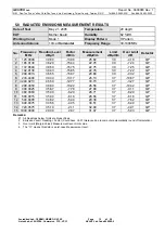
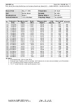
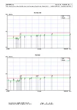
5.7  RADIATED EMISSION DATA 

The frequency range of radiated emissions from 

30 MHz to 1 GHz

  was investigated. The initial 

step in collecting emission data was a spectrum analyzer peak scan of the frequency range for 
all the test modes. Then the worst modes were reported the following data pages. 


Summary of Contents for AIMB-562 series

Page 1: ... 20 Lane 26 Rueiguang Road Neihu District Taipei 114 Taiwan Report By Global EMC Standard Tech Corp No 3 Pau Tou Tsuo Valley Chia Pau Tsuen Lin Kou Hsiang Taipei County Taiwan R O C Tel 886 2 2603 5321 Fax 886 2 2603 5325 Test results given in this report only relate to the specimen s tested measured This report is the property of GesTek and shall not be reproduced other than in full without the w...

Page 2: ...Y LEVELS 27 7 5 OPERATING CONDITIONS OF THE EUT 27 7 6 TEST PROCEDURE 27 7 7 TEST RESULT 28 8 RF FIELD STRENGTH SUSCEPTIBILITY TEST 29 8 1 TEST EQUIPMENT 29 8 2 TEST METHOD 29 8 3 BLOCK DIAGRAM OF TEST SETUP 29 8 4 SEVERITY LEVELS 30 8 5 OPERATING CONDITIONS OF THE EUT 30 8 6 TEST PROCEDURE 30 8 7 TEST RESULT 31 9 ELECTRICAL FAST TRANSIENT BURST IMMUNITY TEST32 9 1 TEST EQUIPMENT 32 9 2 TEST METHO...

Page 3: ...ENERAL REMARKS The tests were performed according to the technical requirement of EUT Electro magnetic Radiated Emission Interference Measurement EN 55022 Electro magnetic Conducted Emission Interference Measurement EN 55022 Harmonic Current Emissions EN 61000 3 2 Voltage Fluctuation and Flicker Measurement EN 61000 3 3 ESD Immunity Test IEC 61000 4 2 RF Field strength Susceptibility Test IEC 6100...

Page 4: ...icker Measurement PASS With regards to the EN 61000 3 2 the PC must be tested at full load in order to reach the assigned current of the Power supply With Dummy Load Active Power 75W EN 55024 IEC 61000 4 2 1995 A1 1998 A2 2000 Electrostatic Discharge ESD PASS Contact discharge up to 4kV Air discharge up to 8kV EN 55024 IEC 61000 4 3 2002 A1 2002 RF field strength Susceptibility PASS 80 1000MHz 1kH...

Page 5: ...r Cord 3Pins Non Shielded 1 8m Detachable 3 2 TEST MODES EUT COMPONENTS DESCRIPTION EUT Mother Board M N AIMB 562 Series Test Mode Mode 1 CPU INTEL 3 8G 800MHz Mother Board EUT ASUS M N P5LD2 VM DH BSMI ID D33005 SATA H D D Seagate M N ST3120026AS BSMI ID D33027 F D D Panasonic M N JU 256A398PC BSMI ID D33083 CD ROM ASUS M N CD S520 A BSMI ID 41016007 Memory elixir 512MB x 4 PC 4300 DDRII Audio On...

Page 6: ...ard VGA On Board PC System S P S Seventeam M N ST 402HLP BSMI ID D33108 Input 115 240V 10A 50 60Hz D Sub Monitor M01 029 Manufacturer ADI Model Number MICRO SCAN G1000 Serial Number N A BSMI ID 3892A351 FCC ID N A Data Cable Shielded detachable 1 5m VGA Cable Power Cord 3Pin Shielded Detachable 1 5m PS2 Keyboard K01 087 Manufacturer IBM Model Number SK 8811 Serial Number 01979618 BSMI ID 3902B330 ...

Page 7: ... N A Headset Earphone E01 106 Manufacturer Good Vision Model Number LY MIC02 Serial Number N A Data Cable Non Shielded Undetachable 1 8 m Power Cord N A Cassette Recorder R02 027 Manufacturer PANASONIC Model Number RQ L11LT Serial Number N A BSMI ID R31017 FCC ID N A Power Cord N A Battery 1 5V 2 Cassette Recorder R02 028 Manufacturer PANASONIC Model Number RQ L11LT Serial Number N A BSMI ID R3101...

Page 8: ...able 1 5m AC Power Adaptor YHI M N YS 1015 U12A BSMI ID 4872A185 Input AC IN 100V 50 60Hz 35VA Output DC 12V 1 25A External USB 2 0 Hard Disk U02 053 Manufacturer TERASYS Model Number F12 UF Serial Number A0100215 34P0030 BSMI ID 4912A002 Data Cable Shielded detachable 1 5m AC Power Adaptor YHI M N YS 1015 U12A BSMI ID 4872A185 Input AC IN 100V 50 60Hz 35VA Output DC 12V 1 25A External USB 2 0 Har...

Page 9: ... 4912A002 Data Cable Shielded detachable 1 5m AC Power Adaptor YHI M N YS 1015 U12A BSMI ID 4872A185 Input AC IN 100V 50 60Hz 35VA Output DC 12V 1 25A External USB 2 0 Hard Disk U02 057 Manufacturer TERASYS Model Number F12 UF Serial Number A0100215 34P0030 BSMI ID 4912A002 Data Cable Shielded detachable 1 5m AC Power Adaptor YHI M N YS 1015 U12A BSMI ID 4872A185 Input AC IN 100V 50 60Hz 35VA Outp...

Page 10: ...n NEMKO EMC Laboratory Authorization Gaustadalleen 30 Postbox 73 Blindern 0314 Oslo Aut No ELA 126 Aug 15 1997 Recognition on Det Norske Veritas AS Statement No 510 96 1017 Accreditation on NVLAP effective through September 30 2005 For CISPR 22 FCC Method and AS NZS CISPR 22 Measurement NVLAP Lab Code 200085 0 Registration on VCCI effective through June 28 2007 Registration No R 291 and C 305 Reco...

Page 11: ... NNB 2 16Z 99042 12 17 04 4 Pulse Limiter R S ESH3 Z2 357 8810 52 08 06 04 5 RF CABLE GTK N A GTK E A154 01 12 01 04 6 50 Ohm Terminator GTK N A GTK E A130 01 10 09 04 7 Shielded Room GTK N A B5 N A Note All equipment upon which need to calibrated are with calibration period of 1 year 4 2 TEST METHOD According to EN 55022 1998 A1 2000 A2 2003 4 3 BLOCK DIAGRAM OF TEST SETUP Note This is a reprehen...

Page 12: ...utput was terminated by 50 Ohms terminator 4 6 CONDUCTED EMISSION DATA The measurement range of conducted emission which is from 0 15 MHz to 30 MHz was investigated The initial step in collecting conducted data is a spectrum analyzer peak scan of the measurement range for all the test modes Then the worst modes were reported the following data pages The final measurement equal to Receiver reading ...

Page 13: ...surement dBµV Limit dBµV Over Limit dB Detector 1 0 1576 24 71 10 04 34 75 65 59 30 84 QP 2 0 1576 20 35 10 04 30 39 55 59 25 20 AVG 3 0 2338 17 45 10 07 27 52 62 31 34 79 QP 4 0 2338 13 99 10 07 24 06 52 31 28 25 AVG 5 0 3148 16 46 10 10 26 56 59 84 33 28 QP 6 0 3148 12 38 10 10 22 48 49 84 27 36 AVG 7 4 7808 17 65 10 35 28 00 56 00 28 00 QP 8 4 7808 12 06 10 35 22 41 46 00 23 59 AVG 9 15 8205 14...

Page 14: ...BµV Over Limit dB Detector 1 0 1551 25 81 10 04 35 85 65 72 29 87 QP 2 0 1551 22 70 10 04 32 74 55 72 22 98 AVG 3 0 1792 26 46 10 05 36 51 64 52 28 01 QP 4 0 1792 24 94 10 05 34 99 54 52 19 53 AVG 5 0 3900 19 75 10 12 29 87 58 06 28 19 QP 6 0 3900 17 61 10 12 27 73 48 06 20 33 AVG 7 1 9563 28 95 10 12 39 07 56 00 16 93 QP 8 1 9563 17 41 10 12 27 53 46 00 18 47 AVG 9 3 7642 13 05 10 23 23 28 56 00 ...

Page 15: ...ent was performed at Site 1 Site 2 Site 3 Site 4 Item Instrument Manufacturer Model Serial No Last Cal Date 1 Test Receiver R S ESCS30 100035 06 10 04 2 Spectrum Analyzer HP 8542E 3520A00123 342 7A00118 07 21 04 3 Pre Amplifier HP 8447F OPT H64 3113A04487 10 09 04 4 BILOG Antenna SCHAFFNER CBL6112B 2580 11 30 04 5 RF Cable GTK N A GTK E A152 01 12 29 04 6 Open Site GTK N A B2 11 23 04 Note All equ...

Page 16: ...TUP 5 3 1 BLOCK DIAGRAM OF CONNECTIONS BETWEEN EUT AND SIMULATORS Note This is a reprehensive setup diagram for Table top EUT For Floor standing EUT the table will be removed with all others setup condition remain the same Headset Earphone Modem D Sub Monitor HHHHHHHH HHHHHHHH HHHHHHHH HHHHHHHH PS2 Mouse Far End Network Server HUB GIGABIT LAN Printer Headset Earphone PS2 Keyboard Cassette Player E...

Page 17: ...5 4 RADIATED EMISSION LIMITS Class B Limits Frequency Distance Field Strength MHz Meter dB µV m 30 to 230 10 30 230 to 1000 10 37 Class A Limits Frequency Distance Field Strength MHz Meter dB µV m 30 to 230 10 40 230 to 1000 10 47 Remark 1 The tighter limit shall apply at the edge between two frequency bands 2 Distance refers to the distance in meters between the measuring antenna and the closest ...

Page 18: ...l height equaled 80 cm This table can be rotated 360 degrees The measurement antenna was mounted to a non conductive mast capable of moving the antenna vertically Antenna height was varied from 1 meter to 4 meters and the system under test was rotated from 0 degree through 360 degrees relative to the antenna position and polarization Horizontal and Vertical Also the I O cable positions were invest...

Page 19: ...18 QP 2 165 9130 38 20 15 44 22 76 30 7 24 QP 3 172 8500 38 50 15 75 22 75 30 7 25 QP 4 192 0130 38 43 15 65 22 78 30 7 22 QP 5 200 0013 36 55 15 87 20 68 30 9 32 QP 6 233 4400 39 30 13 17 26 13 37 10 87 QP 7 240 0213 46 50 12 77 33 73 37 3 27 QP 8 299 9950 36 80 10 22 26 58 37 10 42 QP 9 400 0025 35 67 7 78 27 89 37 9 11 QP 10 480 0363 35 00 6 29 28 71 37 8 29 QP 11 500 0015 35 00 6 16 28 84 37 8...

Page 20: ...P 5 172 9000 36 30 15 75 20 55 30 9 45 QP 6 192 0005 38 92 15 65 23 27 30 6 73 QP 7 199 9960 37 30 15 87 21 43 30 8 57 QP 8 215 9985 36 80 14 16 22 64 30 7 36 QP 9 233 5000 42 10 13 17 28 93 37 8 07 QP 10 240 0000 46 10 12 77 33 33 37 3 67 QP 11 250 0005 39 63 11 98 27 65 37 9 35 QP 12 300 0300 37 69 10 22 27 47 37 9 53 QP 13 375 0045 35 43 8 28 27 15 37 9 85 QP 14 400 0800 36 35 7 78 28 57 37 8 4...

Page 21: ... Tou Tsuo Valley Chia Pau Tsuen Lin Kou Hsiang Taipei County Taiwan R O C Tel 886 2 2603 5321 Fax 886 2 2603 5325 Accredited Lab Of BSMI NEMKO NVLAP Page 21 of 59 Listed Lab of AUSTEL Commerce FCC VCCI NVLAP Lab Code 200085 0 Horizontal Vertical ...

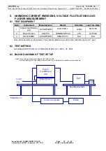
Page 22: ...al Conditioning Unit SCHAFFNER CCN1000 1 72282 05 17 05 2 Power Source PACIFIC 345AMX UPC32 270 12 15 04 3 SOFTWARE SCHAFFNER WIN2100 V3 N A N A Note All measurement critical items of test instrumentation were within their calibration period of 1 year 6 2 TEST METHOD According to EN 61000 3 2 2000 EN 61000 3 3 1995 A1 2001 6 3 BLOCK DIAGRAM OF TEST SETUP Note This is a reprehensive setup diagram f...

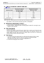
Page 23: ...are disregarded 6 5 OPERATING CONDITIONS OF THE EUT 1 Setup the EUT and Test Equipment as shown on 6 3 2 Power on the EUT Acting performance checking program to allow EUT executing its usual operation mode during test 6 6 TEST PROCEDURE Power Line Harmonics The EUT was supplied in series with power analyzer from a power source having the same nominal voltage and frequency as the rated supply volta...

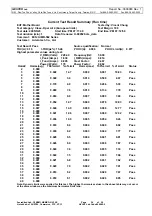
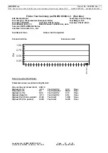
Page 24: ...tatus 2 0 000 3 0 089 0 608 14 7 0 098 0 901 10 83 Pass 4 0 000 5 0 012 0 340 3 4 0 014 0 508 2 67 Pass 6 0 000 7 0 009 0 179 4 9 0 013 0 266 5 03 Pass 8 0 000 9 0 007 0 089 7 8 0 010 0 134 7 79 Pass 10 0 000 11 0 006 0 063 9 8 0 007 0 093 7 89 Pass 12 0 000 13 0 007 0 054 12 7 0 009 0 078 10 93 Pass 14 0 000 15 0 007 0 046 14 0 0 009 0 068 12 77 Pass 16 0 000 17 0 005 0 041 12 6 0 007 0 060 12 32...

Page 25: ...5 5 23 Start time PM 07 14 50 End time PM 07 25 03 Test duration min 10 Data file name F 000530 cts_data Comment M N AIMB 562 Series Customer Advantech Co Ltd Test Result Pass Status Test Completed Psti and limit line European Limits 0 25 0 50 0 75 1 00 Pst 19 25 02 Time is too short for Plt plot Parameter values recorded during the test Vrms at the end of test Volt 228 15 Highest dt 0 16 Test lim...

Page 26: ... 05 2 Shielded Room GTK N A B4 02 14 05 Note All measurement critical items of test instrumentation were within their calibration period of 1 year 7 2 TEST METHOD According to EN 55024 1998 A1 2001 A2 2003 IEC 61000 4 2 1995 A1 1998 A2 2000 7 3 BLOCK DIAGRAM OF TEST SETUP Note This is a reprehensive setup diagram for Table top EUT For Floor standing EUT the table will be removed with all others se...

Page 27: ... its usual operation mode during test 7 6 TEST PROCEDURE Direct ESD Single discharge at 1 second interval at least 10 positive 10 negative discharges Air discharges to surfaces of the EUT Air Discharge This test was performed on non conductive surfaces in accordance with IEC 61000 4 2 1995 A1 1998 A2 2000 Contact Discharge Single discharge at 1 second interval at least 25 positive 25 negative disc...

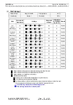
Page 28: ...HCP 25 2kV 4kV 6kV 8kV B A PASS 25 2kV 4kV 6kV 8kV B A PASS Indirect Discharge VCP Front 25 2kV 4kV 6kV 8kV B A PASS 25 2kV 4kV 6kV 8kV B A PASS Indirect Discharge VCP Left 25 2kV 4kV 6kV 8kV B A PASS 25 2kV 4kV 6kV 8kV B A PASS Indirect Discharge VCP Back 25 2kV 4kV 6kV 8kV B A PASS 25 2kV 4kV 6kV 8kV B A PASS Indirect Discharge VCP Right 25 2kV 4kV 6kV 8kV B A PASS Meet criteria A Operate as int...

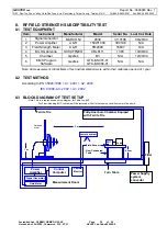
Page 29: ...04 5 Chamber GesTek B3 N A 12 03 04 6 EMS Program Software GesTek GTK E S001 01 GTK E S004 01 N A N A Note All measurement critical items of test instrumentation were within their calibration period of 1 year 8 2 TEST METHOD According to EN 55024 1998 A1 2001 A2 2003 IEC 61000 4 3 2002 A1 2002 8 3 BLOCK DIAGRAM OF TEST SETUP Note This is a reprehensive setup diagram for Table top EUT For Floor sta...

Page 30: ... checking program to allow EUT executing its usual operation mode during test 8 6 TEST PROCEDURE The EUT and load were placed on a table which was 0 8 meters high The field sensor was also placed on the same table to monitor field strength from transmitting antenna EUT was set 3 meters away from the transmitting antenna The transmitting antenna was fixed at 1 meter above ground Both horizontal and...

Page 31: ...600 863 and 900 1 MHz Freq Range MHz Position Angle Polarity H or V Field Strength V m Performance Criteria Complied to Results 80 0 90 180 270 H V 3 A PASS 120 0 90 180 270 H V 3 A PASS 160 0 90 180 270 H V 3 A PASS 230 0 90 180 270 H V 3 A PASS 434 0 90 180 270 H V 3 A PASS 460 0 90 180 270 H V 3 A PASS 600 0 90 180 270 H V 3 A PASS 863 0 90 180 270 H V 3 A PASS 900 0 90 180 270 H V 3 A PASS Mee...

Page 32: ... GENERATOR EM TEST UCS 500 M 0500 15 07 10 04 Note All measurement critical items of test instrumentation were within their calibration period of 1 year 9 2 TEST METHOD According to EN 55024 1998 A1 2001 A2 2003 IEC 61000 4 4 2004 9 3 BLOCK DIAGRAM OF TEST SETUP Note This is a reprehensive setup diagram for Table top EUT For Floor standing EUT the table will be removed with all others setup condit...

Page 33: ...of the test a functional test was performed on the EUT to ensure proper operation The EUT was also monitored during the test for any degradation of performance For AC Power lines test The EUT is connected to the power mains through a coupling decoupling network that directly injected the transient energy Bursts of pulse trains were injected onto the power line in both positive and negative polarit...

Page 34: ...T B A PASS L PE 1 DIRECT B A PASS L N PE 0 5 1 0 2 0 1 DIRECT B A PASS L 1 DIRECT B A PASS N 1 DIRECT B A PASS PE 1 DIRECT B A PASS L N 1 DIRECT B A PASS N PE 1 DIRECT B A PASS L PE 1 DIRECT B A PASS L N PE 0 5 1 0 2 0 1 DIRECT B A PASS Inject Place I O Cable Capacitive Clamp Used GIGABIT LAN 1 Clamp B A PASS GIGABIT LAN 0 5 1 0 1 Clamp B A PASS Meet criteria A Operate as intended during and after...

Page 35: ...7 10 04 Note All equipment upon which need to calibrated are with calibration period of 1 year 10 2 TEST METHOD According to EN 55024 1998 A1 2001 A2 2003 IEC 61000 4 5 1995 A1 2000 10 3 BLOCK DIAGRAM OF TEST SETUP Note This is a reprehensive setup diagram for Table top EUT For Floor standing EUT the table will be removed with all others setup condition remain the same 10 4 SEVERITY LEVELS Open Ci...

Page 36: ...e during test 10 6 TEST PROCEDURE A combination wave as specified in IEC 61000 4 5 1995 A1 2000 was applied to the EUT The amplitude was gradually increased using control software Surges were initiated line synced One surge per polarity and voltage level was applied in common and differential mode to the EUT at 0 90 180 270 and 0 degree phase angles The surges were applied at a rate of 1 surge per...

Page 37: ... 1 0 Coupling 5 B A PASS 1 90 Coupling 5 B A PASS 1 180 Coupling 5 B A PASS 0 5 1 0 2 0 1 270 Coupling 5 B A PASS 1 0 Coupling 5 B A PASS 1 90 Coupling 5 B A PASS 1 180 Coupling 5 B A PASS L PE Common mode 0 5 1 0 2 0 1 270 Coupling 5 B A PASS 1 0 Coupling 5 B A PASS 1 90 Coupling 5 B A PASS 1 180 Coupling 5 B A PASS 0 5 1 0 2 0 1 270 Coupling 5 B A PASS 1 0 Coupling 5 B A PASS 1 90 Coupling 5 B A...

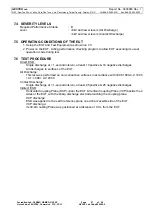
Page 38: ...D According to EN 55024 1998 A1 2001 A2 2003 IEC 61000 4 6 2003 A1 2004 11 3 BLOCK DIAGRAM OF TEST SETUP Note This is a reprehensive setup diagram for Table top EUT For Floor standing EUT the table will be removed with all others setup condition remain the same 11 4 SEVERITY LEVELS Test specification Required Performance Criteria A Level 1kHz sine wave with 80 Amplitude Modulation 3V Frequency ran...

Page 39: ...e test a functional test was performed on the EUT to ensure proper operation The EUT was also monitored during the test for any degradation of performance Also prior to the start of the test clamp injection RF current probe calibration measurements were performed as described in IEC 61000 4 6 2003 A1 2004 For AC Power line test For Signal Lines and Control Lines test The disturbance signal is thro...

Page 40: ...t The acceptance criteria were met and the EUT passed the test Frequency Range MHz Inject Line Field Strength Inject Method Required Criteria Performance Criteria Complied To Result 0 15 80 AC Line 3V CLAMP A A PASS 0 15 80 GIGABIT LAN 3V CLAMP A A PASS Additional comprehensive functional test selected frequencies are 0 2 1 7 1 13 56 21 0 27 12 and 40 68MHz 1 Frequency Range MHz Inject Line Field ...

Page 41: ...ition remain the same 12 4 SEVERITY LEVELS Voltage Dips and Interruption Reduction Test Duration Required Performance Criteria 95 10 ms B 30 500 ms C 95 5s C 12 5 OPERATING CONDITIONS OF THE EUT 1 Setup the EUT and Test Equipment as shown on 12 3 2 Power on the EUT Acting performance checking program to allow EUT executing its usual operation mode during test 12 6 TEST PROCEDURE The EUT and its lo...

Page 42: ... Short Interruptions 315 95 5000 C 0 B A PASS 45 B 90 B 135 B 180 B A PASS 225 B 270 B 315 95 10 B 0 C A PASS 45 C 90 C 135 C 180 C A PASS 225 C 270 C Voltage Dips 315 30 500 C Meet criteria A Operate as intended during and after the test Meet criteria B Operate as intended after the test Meet criteria C Loss of function provided the function is self recoverable or can be restored by the operation...

Page 43: ...u Tsuen Lin Kou Hsiang Taipei County Taiwan R O C Tel 886 2 2603 5321 Fax 886 2 2603 5325 Accredited Lab Of BSMI NEMKO NVLAP Page 43 of 59 Listed Lab of AUSTEL Commerce FCC VCCI NVLAP Lab Code 200085 0 13 PHOTOGRAPHS FOR TEST 13 1 TEST PHOTOGRAPHS FOR CONDUCTION Mode 1 ...

Page 44: ...alley Chia Pau Tsuen Lin Kou Hsiang Taipei County Taiwan R O C Tel 886 2 2603 5321 Fax 886 2 2603 5325 Accredited Lab Of BSMI NEMKO NVLAP Page 44 of 59 Listed Lab of AUSTEL Commerce FCC VCCI NVLAP Lab Code 200085 0 13 2 TEST PHOTOGRAPHS FOR RADIATED Mode 1 ...

Page 45: ...y Chia Pau Tsuen Lin Kou Hsiang Taipei County Taiwan R O C Tel 886 2 2603 5321 Fax 886 2 2603 5325 Accredited Lab Of BSMI NEMKO NVLAP Page 45 of 59 Listed Lab of AUSTEL Commerce FCC VCCI NVLAP Lab Code 200085 0 13 3 TEST PHOTOGRAPHS FOR HARMONIC FLICKER Mode 1 ...

Page 46: ... Valley Chia Pau Tsuen Lin Kou Hsiang Taipei County Taiwan R O C Tel 886 2 2603 5321 Fax 886 2 2603 5325 Accredited Lab Of BSMI NEMKO NVLAP Page 46 of 59 Listed Lab of AUSTEL Commerce FCC VCCI NVLAP Lab Code 200085 0 13 4 TEST PHOTOGRAPHS FOR ESD Mode 1 ...

Page 47: ...y Chia Pau Tsuen Lin Kou Hsiang Taipei County Taiwan R O C Tel 886 2 2603 5321 Fax 886 2 2603 5325 Accredited Lab Of BSMI NEMKO NVLAP Page 47 of 59 Listed Lab of AUSTEL Commerce FCC VCCI NVLAP Lab Code 200085 0 13 5 TEST PHOTOGRAPHS FOR ESD TEST POINTS Mode 1 ...

Page 48: ...o Valley Chia Pau Tsuen Lin Kou Hsiang Taipei County Taiwan R O C Tel 886 2 2603 5321 Fax 886 2 2603 5325 Accredited Lab Of BSMI NEMKO NVLAP Page 48 of 59 Listed Lab of AUSTEL Commerce FCC VCCI NVLAP Lab Code 200085 0 13 6 TEST PHOTOGRAPHS FOR RS Mode 1 ...

Page 49: ... Valley Chia Pau Tsuen Lin Kou Hsiang Taipei County Taiwan R O C Tel 886 2 2603 5321 Fax 886 2 2603 5325 Accredited Lab Of BSMI NEMKO NVLAP Page 49 of 59 Listed Lab of AUSTEL Commerce FCC VCCI NVLAP Lab Code 200085 0 13 7 TEST PHOTOGRAPHS FOR EFT Mode 1 ...

Page 50: ...Valley Chia Pau Tsuen Lin Kou Hsiang Taipei County Taiwan R O C Tel 886 2 2603 5321 Fax 886 2 2603 5325 Accredited Lab Of BSMI NEMKO NVLAP Page 50 of 59 Listed Lab of AUSTEL Commerce FCC VCCI NVLAP Lab Code 200085 0 13 8 TEST PHOTOGRAPHS FOR SURGE Mode 1 ...

Page 51: ...o Valley Chia Pau Tsuen Lin Kou Hsiang Taipei County Taiwan R O C Tel 886 2 2603 5321 Fax 886 2 2603 5325 Accredited Lab Of BSMI NEMKO NVLAP Page 51 of 59 Listed Lab of AUSTEL Commerce FCC VCCI NVLAP Lab Code 200085 0 13 9 TEST PHOTOGRAPHS FOR CS Mode 1 ...

Page 52: ... Valley Chia Pau Tsuen Lin Kou Hsiang Taipei County Taiwan R O C Tel 886 2 2603 5321 Fax 886 2 2603 5325 Accredited Lab Of BSMI NEMKO NVLAP Page 52 of 59 Listed Lab of AUSTEL Commerce FCC VCCI NVLAP Lab Code 200085 0 13 10TEST PHOTOGRAPHS FOR DIPS Mode 1 ...

Page 53: ...en Lin Kou Hsiang Taipei County Taiwan R O C Tel 886 2 2603 5321 Fax 886 2 2603 5325 Accredited Lab Of BSMI NEMKO NVLAP Page 53 of 59 Listed Lab of AUSTEL Commerce FCC VCCI NVLAP Lab Code 200085 0 14 PHOTOGRAPHS FOR PRODUCT 1 Front View Of PC System 2 Back View Of PC System ...

Page 54: ...u Tsuo Valley Chia Pau Tsuen Lin Kou Hsiang Taipei County Taiwan R O C Tel 886 2 2603 5321 Fax 886 2 2603 5325 Accredited Lab Of BSMI NEMKO NVLAP Page 54 of 59 Listed Lab of AUSTEL Commerce FCC VCCI NVLAP Lab Code 200085 0 3 Back View Of PC System ...

Page 55: ... Chia Pau Tsuen Lin Kou Hsiang Taipei County Taiwan R O C Tel 886 2 2603 5321 Fax 886 2 2603 5325 Accredited Lab Of BSMI NEMKO NVLAP Page 55 of 59 Listed Lab of AUSTEL Commerce FCC VCCI NVLAP Lab Code 200085 0 4 Inner View Of PC System 5 Inner View Of PC System ...

Page 56: ...suen Lin Kou Hsiang Taipei County Taiwan R O C Tel 886 2 2603 5321 Fax 886 2 2603 5325 Accredited Lab Of BSMI NEMKO NVLAP Page 56 of 59 Listed Lab of AUSTEL Commerce FCC VCCI NVLAP Lab Code 200085 0 6 Component Side Of Mother Board EUT 7 Component Side Of Mother Board EUT ...

Page 57: ...suen Lin Kou Hsiang Taipei County Taiwan R O C Tel 886 2 2603 5321 Fax 886 2 2603 5325 Accredited Lab Of BSMI NEMKO NVLAP Page 57 of 59 Listed Lab of AUSTEL Commerce FCC VCCI NVLAP Lab Code 200085 0 8 Component Side Of Mother Board EUT 9 Component Side Of Mother Board EUT ...

Page 58: ...o Valley Chia Pau Tsuen Lin Kou Hsiang Taipei County Taiwan R O C Tel 886 2 2603 5321 Fax 886 2 2603 5325 Accredited Lab Of BSMI NEMKO NVLAP Page 58 of 59 Listed Lab of AUSTEL Commerce FCC VCCI NVLAP Lab Code 200085 0 10 Solder Side Of Mother Board EUT ...

Page 59: ...ou Hsiang Taipei County Taiwan R O C Tel 886 2 2603 5321 Fax 886 2 2603 5325 Accredited Lab Of BSMI NEMKO NVLAP Page 59 of 59 Listed Lab of AUSTEL Commerce FCC VCCI NVLAP Lab Code 200085 0 15 EMI EMS REDUCTION METHOD DURING COMPLIANCE TESTING No modification was made during testing ...

Reviews: