2 AIMB-705 Startup Manual
The board has a number of jumpers that allow you to con-
figure your system to suit your application. The table below
lists the function of each jumper and connector.
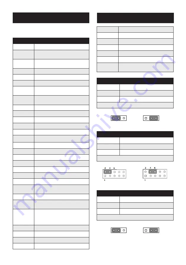
Connector / Jumper List
Label
Function
EATXPWR1
ATX 24-pin main power connector (for
system)
ATX12V1
ATX 12 V auxiliary power connector
(for CPU)
DIMMA1
Channel A DIMM1
DIMMB1
Channel B DIMM1
SATA0 ~ 3
SATA III (Gen3)
LAN1_
USB3_34
LAN1 / USB 3.0 port 1, 2 stack
connector
LAN2_
USB34
LAN2 / USB 2.0 port 1, 2 stack
connector
USB3_12
USB 3.0 (pin header)
USB5
USB 2.0 (type A)
USB910
USB 2.0
PCIEX16_1
PCIe x16 slot (Gen3)
PCIEX4_1
PCIe x4 slot (Gen2)
PCI1 ~ 5
PCI slot (32-bit/33 MHz)
VGA1+DVI1
VGA connector / DVI connector
VGA1
VGA connector
COM12
Serial port: RS-232
COM3
Serial port: RS-232/422/485
COM4 ~ 6
Serial port: RS-232
LPT1
Parallel port supporting SPP/EPP mode
KBMS1
Keyboard and Mouse PS/2 connector
KBMS2
Keyboard and Mouse PS/2 connector
(box header)
JFP1
Power switch / reset connector
JFP2
External speaker / HDD LED connector
/ SM Bus connector
JFP3
Keyboard lock and power LED
Suspend: fast flash (ATX/AT)
System On: on (ATX/AT)
System Off: off (AT/ATX)
VOLT1
Voltage Display
CPUFAN1
CPU fan connector (4 pin)
SYSFAN1 ~2
System fan connector (4 pin)
LANLED1
Front panel LAN indicator connector
AUDIO1
Audio connector (Line-out, Mic-in)
FPAUD1
Front panel audio pin header
SPI_CN1
SPI flash card pin header
SPDIF_OUT1
SPDIF audio output pin header
GPIO1
8 bit GPIO from super I/O
SMBUS1
SM bus from PCH
LPC1
Low pin count connector for Advantech
TPM LPC and RS232 modules.
JCMOS1/JME1: CMOS clear/ME update function
Pins
Result
1-2
Keep CMOS data/Enable ME update*
2-3
Clear CMOS data/Disable ME update
* Default
*Keep CMOS data/ *Clear CMOS data/
Enable ME update Disable ME update
JWDT1: Watchdog timer output option
Closed Pins
Result
2-4
NC
4-6
System reset*
* Default
NC 2-4 Closed *System Reset 4-6 Closed
PSON1: ATX, AT mode selector
Closed Pins
Result
1-2
AT Mode
2-3
ATX Mode*
* Default
AT Mode 1-2 closed *ATX Mode 2-3 closed
1
2
3
1
2
3
1
2
3
1
2
3
Jumpers and Connectors
Jumpers and Connectors (Cont.)


