background image

xi

AIMB-B1000 User Manual

/ 用户手册




電源線或者插頭損壞;



設備內部有液體流入;



設備曾暴露在過於潮濕的環境中使用;



設備無法正常工作,或您無法通過用戶手冊來使其正常工作;



設備跌落或者損壞;



設備有明顯的外觀破損。

15.

請不要把設備保存在超出我們建議的溫度範圍的環境,即不要低於 -20°C (-4 
°F)或高於 60°C (140°F),否則可能會損壞設備。

16.

注意:電腦配置了由電池供電的即時時鐘電路,如果電池放置不正確,將有爆 
炸的危險。因此,只可以使用製造商推薦的同一種或者同等型號的電池進行替 
換。請按照製造商的指示處理舊電池。

17.

若產品出貨未附帶電源裝置,請參考操作手冊中的相關說明 , 需要選用由 UL 認
證的電源供應器供電 , 並且可在 40°C 環境溫度下操作之電源。

根據 IEC 704-1:1982 的規定,操作員所在位置的聲壓級不可高於 70dB(A)。
免責聲明:該安全指示符合 IEC 704-1 的要求。研華公司對其內容的準確性不承擔任
何法律責任。

Safety Precaution - Electricity

/ 安全措施 - 静电防护 /

安全措施 - 靜電防護

Follow these simple precautions to protect yourself from harm and the products from
damage.

1.

To avoid electrical shock, always disconnect the power from your PC chassis 
before you work on it. 

2.

For the sake of the equipment, disconnect power before making any configura-
tion changes. The sudden rush of power as you connect a jumper or install a 
card may damage sensitive electronic components.

3.

Electronic components are also vulnerable to damage by electrostatic dis-
charge. An electrostatic charge can build up on the human body, especially 
where the air is dry. At minimum, dissipate potential body charge before han-
dling any electronic board by touching a conductive surface on the chassis. 
Only then remove circuit boards from their antistatic bags. Handle boards by the 
edges or mounting brackets only; do not touch components or connecting pins.

为了保护您和您的设备免受伤害或损坏,请遵照以下安全措施:

操作设备之前,请务必断开机箱电源,以防触电。不可在电源接通时接触 CPU 卡

或其他卡上的任何元件。

在更改任何配置之前请断开电源,以免在您连接跳线或安装卡时,瞬间电涌损坏

敏感电子元件。

為了保護您和您的設備免受傷害或損壞,請遵照以下安全措施:

操作設備之前,請務必斷開機箱電源,以防觸電。不可在電源接通時接觸 CPU 卡 
或其他卡上的任何元件。

在更改任何配置之前請關閉電源,以免在您連接跳線或安裝卡時,瞬間電湧損壞 
敏感電子元件。

Summary of Contents for AIMB-B1000 Series

Page 1: ...User Manual AIMB B1000 Series Ultra Thin Embedded Mini ITX Chassis Mini ITX Mini ITX...

Page 2: ...any form or by any means without the prior written permission of Advantech Co Ltd Information provided in this manual is intended to be accurate and reliable How ever Advantech Co Ltd assumes no resp...

Page 3: ...ials service time and freight Please consult your dealer for more details If you think you have a defective product follow these steps 1 Collect all the information about the problem encountered For e...

Page 4: ...00 Two Bottom Mounting Brackets P N 1960014487T001 Four Bottom Rubber Foot P N 1990012452S000 Four M4 Screws for Bottom Rubber Foot Mounting Brackets P N 1930003238 Six Eight M3 Screws for Assembling...

Page 5: ...nclosure In order to protect the product from being damaged by ESD Electrostatic Discharge and EMI leakage we strongly recommend the use of CE compliant industrial enclo sure products CE ESD EMI CE CE...

Page 6: ...ter ference to radio communications However there is no guarantee that interference will not occur in a particular installation If this equipment does cause harmful interfer ence to radio or televisio...

Page 7: ...ech s customer service center for technical support if you need additional assistance Please have the following information ready before you call Product name and serial number Description of your per...

Page 8: ...e welcome comments and constructive criticism Please send all such in writing to support advantech com support advantech com support advantech com Warning Warnings if not observed indicate conditions...

Page 9: ...e equipment For safety reasons the equipment should be opened only by qualified service personnel 14 If one of the following situations arises get the equipment checked by service personnel The power...

Page 10: ...AIMB B1000 User Manual x 1 2 3 4 5 6 7 8 9 10 11 12 13 14 15 20 C 4 F 60 C 140 F 16 17 UL 40 C IEC 704 1 1982 70dB A IEC 704 1 1 2 3 4 5 6 7 8 9 10 11 12 13 14...

Page 11: ...ura tion changes The sudden rush of power as you connect a jumper or install a card may damage sensitive electronic components 3 Electronic components are also vulnerable to damage by electrostatic di...

Page 12: ...AIMB B1000 User Manual xii...

Page 13: ...2 Installing the CPU Memory CPU CPU 6 2 3 Installing the HDD HDD HDD 7 Figure 2 3 Installing HDD HDD HDD 7 2 4 Installing the mini PCIe Device Memory of Bottom Side mini PCIe mini PCIe 7 Figure 2 4 Re...

Page 14: ...ploded Diagram AIMB B1201 AIMB B1201 12 Figure A 1 AIMB B1201 Exploded Diagram Parts List AIMB B1201 AIMB B1201 12 A 2 AIMB B1230 Exploded Diagram AIMB B1230 AIMB B1230 13 Figure A 2 AIMB B1230 Explod...

Page 15: ...Chapter 1 1 General Information...

Page 16: ...emory 2 x 204 PIN DDR3 SODIMM Non ECC up to 16 GB 1333 1600 MHz SDRAM 2 x 204 PIN DDR3 SODIMM Non ECC up to 16 GB 1333 1600 MHz SDRAM Storage device 2 5 HDD bay 2 5 2 5 1 support 2 5 HDD SSD max 9 5 m...

Page 17: ...ntrol 1 Power Button 1 1 1 Power Button 1 1 Power Requirements Voltage 19 VDC power input 19 VDC 19 VDC 12 VDC power input 12 VDC 12 VDC Physical Characteristics Dimensions W x H x D W x H x D 250 x 3...

Page 18: ...C 100 240VAC 1 5A 50 60Hz DC 19V 3 42A 1757002944 Adapter DC 19V for AIMB B1201 90W AC 100 240VAC 1 5A 50 60Hz DC 19V 4 74A 1757003995 Adapter DC 12V for AIMB B1230 60W AC 100 240VAC 1 5A 50 60Hz DC 1...

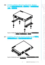
Page 19: ...Chapter 2 2 System Setup and Maintenance...

Page 20: ...AIMB B1000 User Manual 6 2 1 Removing the Chassis Cover Figure 2 1 Removing the chassis cover 2 2 Installing Changing the CPU Memory CPU CPU Figure 2 2 Installing the CPU Memory CPU CPU CPU Memory...

Page 21: ...lling the HDD HDD HDD Figure 2 3 Installing HDD HDD HDD 2 4 Installing the mini PCIe Device Memory of Bottom Side mini PCIe mini PCIe Figure 2 4 Removing the chassis cover and installing the mini PCIe...

Page 22: ...AIMB B1000 User Manual 8 2 5 Installing the Other Device Figure 2 5 Installing the antenna of wifi card Figure 2 6 Installing the CFast device CFast CFast...

Page 23: ...System Setup and Maintenance 2 6 Installing Bottom Mounting Brackets Rubber Foot Figure 2 7 Installing Bottom Mounting Brackets Rubber Foot 2 7 Installing the Power Cord Lock Harness Figure 2 8 Insta...

Page 24: ...AIMB B1000 User Manual 10...

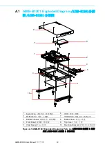
Page 25: ...Appendix A A Exploded Diagram...

Page 26: ...MB B1201 AIMB B1201 Figure A 1 AIMB B1201 Exploded Diagram Parts List AIMB B1201 AIMB B1201 1 System Fan 6 HDD 2 Motherboard 7 HDD Holder 3 Bottom Chassis 8 Bottom Cover 4 Front Panel 9 Top Cover 5 Cf...

Page 27: ...B B1230 Exploded Diagram AIMB B1230 AIMB B1230 Figure A 2 AIMB B1230 Exploded Diagram Parts List AIMB B1230 AIMB B1230 1 System Fan 6 HDD 2 Motherboard 7 Bottom Cover 3 Bottom Chassis 8 Top Cover 4 Fr...

Page 28: ...e without notice No part of this publication may be reproduced in any form or by any means electronic photocopying recording or otherwise without prior written permis sion of the publisher All brand a...

Reviews: