


AIMB-B1000 User Manual
/ 用户手册
2
1.1
Specifications
/ 产品规格 / 產品規格
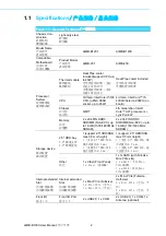
Table 1.1: General Features
/ 一般特性
Chassis Con-
struction
机箱结构
機箱結構
Light-duty steel
轻型钢
輕型鋼
Model Name
产品型号
產品型號
AIMB-B1201
AIMB-B1230
Compatible
Motherboard
內部主板
內部主機板
Product Model
产品型号
產品型號
AIMB-201
AIMB-230
Processor
System
处理器系统
處理器系統
Thermal module
散热模块
散熱模組
Heat Pipe cooler
included(support CPU up
to 45W)
含导热管冷却器 (支持
高达 45W 的 CPU)
含導熱管冷卻器 (支持
高達 45W 的 CPU)
Heat Pipe cooler included
含导热管冷却器
含導熱管冷卻器
CPU
3rd Gen. Intel Core i7/i5/i3
CPU, (uPGA 988B
socket, up to 45W)
4rd Gen. Intel Core™ i5-
4300U/Celeron 2980U (on
board)
Chipset
芯片组
晶片組
QM77
4th Generation Intel®
Core™ ULT proc
Lynx Point-LP
Memory
内存
記憶體
2 x 204 PIN DDR3
SODIMM (Non-ECC), up
to 16 GB (1333/1600 MHz
SDRAM)
2 x 204 PIN DDR3
SODIMM (Non-ECC), up to
16 GB (1333/1600 MHz
SDRAM)
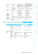
Storage device
储存装置
儲存裝置
2.5" HDD bay
2.5
"
磁盘支架
2.5
"
硬碟支架
1 (support 2.5" HDD/SSD,
max 9.5 mm height)
1 (支持 2.5
"
HDD/SSD,
最大高度为 9.5 mm)
1
(
支援 2.5
"
HDD/SSD
,
最大高度為
9.5 mm
)
1 (support 2.5" HDD/SSD,
max 9.5 mm height)
1 (支持 2.5
"
HDD/SSD,最
大高度为 9.5 mm)
1
(
支援 2.5
"
HDD/SSD
,最
大高度為
9.5 mm
)
Other
其它
1 x Cfast (Front Panel)
1 x Cfast (前面板)
1 x mSATA (with Full-size
Mini-PCIe slot)
1 x mSATA (于长 Mini-
PCIe 插槽)
1 x mSATA (於長 Mini-
PCIe 插槽)
Internal extended
Slot
内部扩展插槽
內部擴展插槽
Internal extended
Slot
内部扩展插槽
內部擴展插槽
1 x Mini-PCIe (Full-size)
1 x Mini-PCIe (全长)
1 x Mini-PCIe (全長)
2 x Mini-PCIe (Full-size,
Half-size)
2 x Mini-PCIe (全长、半
长)
2 x Mini-PCIe (全長、半
長)
Front I/O
前方 I/O
Front I/O Port
前方 I/O
2 x USB2.0, 1 x COM
2 x USB2.0, 1 x COM, 1 x
Antenna (optional)
Summary of Contents for AIMB-B1000 Series
Page 1: ...User Manual AIMB B1000 Series Ultra Thin Embedded Mini ITX Chassis Mini ITX Mini ITX...
Page 12: ...AIMB B1000 User Manual xii...
Page 15: ...Chapter 1 1 General Information...
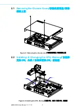
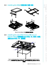
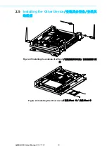
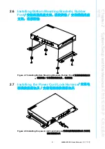
Page 19: ...Chapter 2 2 System Setup and Maintenance...
Page 24: ...AIMB B1000 User Manual 10...
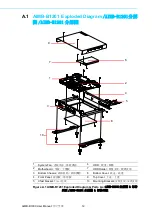
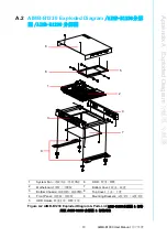
Page 25: ...Appendix A A Exploded Diagram...


