


3
AIMB-B1000 User Manual
/ 用户手册
Chapter 1
G
eneral
Information
概述 產品資訊
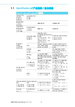
1.2
Environmental
Specification/
环境规格 / 環境規格
Rear I/O
后方 I/O
後方 I/O
Rear I/O Port
后方 I/O
後方 I/O
3 x HDMI, 1 x Lan, 1 x
USB3.0, 1 x Audio (Line-
Out), 2 x Antenna
(optional), 1 x DC-in Jack
1 x HDMI (Compatible with
DP), 1 x DP, 2 x Lan, 2 x
Audio (Line-Out, Mic-In), 2
x Antenna (optional), 1 x
DC-in Jack
Miscellaneous
其它
LED Indicators
LED 指示灯
LED 指示燈
2 (Power LED, HDD LED) 2 (Power LED, HDD LED)
Control
控制
1 (Power Button)
1 (电源按钮)
1 (電源按鈕)
1 (Power Button)
1 (电源按钮)
1 (電源按鈕)
Power
Requirements
电源要求
電源要求
Voltage
电压
電壓
19 V
DC
power input
19
V
DC
电源输入
19
V
DC
電源輸入
12 V
DC
power input
12
V
DC
电源输入
12
V
DC
電源輸入
Physical
Characteristics
物理特性
Dimensions (W x
H x D)
尺寸 (W x H x D)
250 x 35 x 190 mm (9.84"
x 1.38" x 7.48")
250 x 35 x 190 mm (9.84" x
1.38" x 7.48")
Weight
重量
1.8 kg
1.8 kg
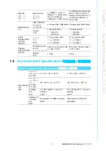
Table 1.2: Environmental Specification/
环境规格 / 環境規格
Environment
环境
環境
Operating
Temperature
操作溫度
0 ~ 40
°
C (32 ~ 104
°
F)
0 ~ 40
°
C (32 ~ 104
°
F)
Non-operat
-
ing Temper
-
ature
储存温度
儲存溫度
-20 ~ 60
°
C (-4 ~ 140
°
F)
-20 ~ 60
°
C (-4 ~ 140
°
F)
Humidity
湿度
濕度
10 ~ 85% @ 40
°
C, non-con-
densing
非凝结
10 ~ 95% @ 60
°
C,
non-con-
densing
非凝结
Vibration
(5
~5 00Hz)
振动
振動
0.2G (with 2.5" HDD) /1G (with
SSD)
0.5G (with 2.5" HDD) /1G
(with SSD)
Summary of Contents for AIMB-B1000 Series
Page 1: ...User Manual AIMB B1000 Series Ultra Thin Embedded Mini ITX Chassis Mini ITX Mini ITX...
Page 12: ...AIMB B1000 User Manual xii...
Page 15: ...Chapter 1 1 General Information...
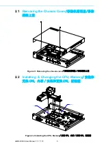
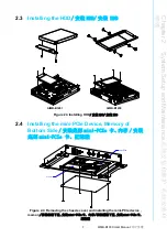
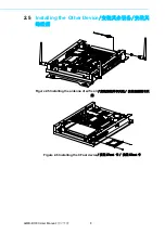
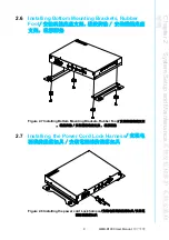
Page 19: ...Chapter 2 2 System Setup and Maintenance...
Page 24: ...AIMB B1000 User Manual 10...
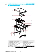
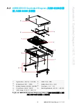
Page 25: ...Appendix A A Exploded Diagram...