background image

AIMB-B1000 User Manual

/ 用户手册

iv

從購買之日起,研華為原購買商提供兩年的產品品質保證。但對那些未經授權的維修
人員維修過的產品並不進行品質保證。研華對於不正確的使用、災難、錯誤安裝產生
的問題有免責權利。
如果研華產品出現故障,在保固期內我們提供免費維修或更換服務。對於保固外產品,
我們將會酌收材料費、人工服務費用。請聯繫您的銷售人員瞭解詳細情況。

如果您認為您購買的產品出現了故障,請遵循以下步驟:

1.

收集您所遇到的問題的資訊 (例如,CPU 頻率、使用的研華產品及其它軟體、硬
體等)。請注意螢幕上出現的任何不正常資訊顯示。

2.

打電話給您的供應商,描述故障問題。請參考手冊,產品和任何有幫助的資訊。

3.

如果您的產品被診斷發生故障,請從您的供應商那裏獲得 RMA (Return Mate

-

rial Authorization) 序號。這可以讓我們儘快的進行故障產品的回收。

4.

請仔細的包裝故障產品,並在包裝中附上完整的售後服務卡片和購買日期證明 

(如銷售發票)。我們對無法提供購買日期證明的產品不提供保固服務。

5.

把相關的 RMA 序號寫在外包裝上,並將其運送給銷售人員。

Packing List

/ 包装清单 / 包裝清單

Before setting up the system, check that the items listed below are included and in
good condition. If any item is not in accord with the table, please contact your dealer
immediately.

安装系统之前,用户需确认包装中含有本设备以及下面所列各项,并确认设备完好。
若有任何不符,请立即与经销商联系。

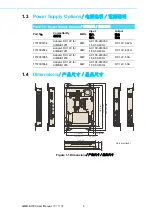
One AIMB-AIMB-B1201/AIMB-B1230 Unit

One CD of User Manual

P/N: 2006B10000

Two Bottom Mounting Brackets

P/N: 1960014487T001

Four Bottom Rubber Foot

P/N: 1990012452S000

Four M4 Screws for Bottom Rubber Foot/ Mounting 
Brackets

P/N: 1930003238

Six Eight M3 Screws for Assembling the Hard Disk 
Drive / spare

P/N: 1930004607

One Lock harness for power cord

P/N: 1990021263S000 
P/N: 1990021264S000

One warranty card

P/N: 2190000902

1 x AIMB-B1201/AIMB-B1230 机箱
1 x 用户手册光盘

P/N: 2006B10000

2 x 底部安装支架

P/N: 1960014487T001

4 x 底部橡胶垫

P/N: 1990012452S000

4 x 用于安装底部橡胶垫 / 支架的 M4 螺丝

P/N: 1930003238

6 x 安装 HDD/ 备用的 M3 螺丝

P/N: 1930004607

1 x 电源线防脱落扣具

P/N: 1990021263S000
P/N: 1990021264S000

1 x 质保卡

P/N: 2190000902

Summary of Contents for AIMB-B1000 Series

Page 1: ...User Manual AIMB B1000 Series Ultra Thin Embedded Mini ITX Chassis Mini ITX Mini ITX...

Page 2: ...any form or by any means without the prior written permission of Advantech Co Ltd Information provided in this manual is intended to be accurate and reliable How ever Advantech Co Ltd assumes no resp...

Page 3: ...ials service time and freight Please consult your dealer for more details If you think you have a defective product follow these steps 1 Collect all the information about the problem encountered For e...

Page 4: ...00 Two Bottom Mounting Brackets P N 1960014487T001 Four Bottom Rubber Foot P N 1990012452S000 Four M4 Screws for Bottom Rubber Foot Mounting Brackets P N 1930003238 Six Eight M3 Screws for Assembling...

Page 5: ...nclosure In order to protect the product from being damaged by ESD Electrostatic Discharge and EMI leakage we strongly recommend the use of CE compliant industrial enclo sure products CE ESD EMI CE CE...

Page 6: ...ter ference to radio communications However there is no guarantee that interference will not occur in a particular installation If this equipment does cause harmful interfer ence to radio or televisio...

Page 7: ...ech s customer service center for technical support if you need additional assistance Please have the following information ready before you call Product name and serial number Description of your per...

Page 8: ...e welcome comments and constructive criticism Please send all such in writing to support advantech com support advantech com support advantech com Warning Warnings if not observed indicate conditions...

Page 9: ...e equipment For safety reasons the equipment should be opened only by qualified service personnel 14 If one of the following situations arises get the equipment checked by service personnel The power...

Page 10: ...AIMB B1000 User Manual x 1 2 3 4 5 6 7 8 9 10 11 12 13 14 15 20 C 4 F 60 C 140 F 16 17 UL 40 C IEC 704 1 1982 70dB A IEC 704 1 1 2 3 4 5 6 7 8 9 10 11 12 13 14...

Page 11: ...ura tion changes The sudden rush of power as you connect a jumper or install a card may damage sensitive electronic components 3 Electronic components are also vulnerable to damage by electrostatic di...

Page 12: ...AIMB B1000 User Manual xii...

Page 13: ...2 Installing the CPU Memory CPU CPU 6 2 3 Installing the HDD HDD HDD 7 Figure 2 3 Installing HDD HDD HDD 7 2 4 Installing the mini PCIe Device Memory of Bottom Side mini PCIe mini PCIe 7 Figure 2 4 Re...

Page 14: ...ploded Diagram AIMB B1201 AIMB B1201 12 Figure A 1 AIMB B1201 Exploded Diagram Parts List AIMB B1201 AIMB B1201 12 A 2 AIMB B1230 Exploded Diagram AIMB B1230 AIMB B1230 13 Figure A 2 AIMB B1230 Explod...

Page 15: ...Chapter 1 1 General Information...

Page 16: ...emory 2 x 204 PIN DDR3 SODIMM Non ECC up to 16 GB 1333 1600 MHz SDRAM 2 x 204 PIN DDR3 SODIMM Non ECC up to 16 GB 1333 1600 MHz SDRAM Storage device 2 5 HDD bay 2 5 2 5 1 support 2 5 HDD SSD max 9 5 m...

Page 17: ...ntrol 1 Power Button 1 1 1 Power Button 1 1 Power Requirements Voltage 19 VDC power input 19 VDC 19 VDC 12 VDC power input 12 VDC 12 VDC Physical Characteristics Dimensions W x H x D W x H x D 250 x 3...

Page 18: ...C 100 240VAC 1 5A 50 60Hz DC 19V 3 42A 1757002944 Adapter DC 19V for AIMB B1201 90W AC 100 240VAC 1 5A 50 60Hz DC 19V 4 74A 1757003995 Adapter DC 12V for AIMB B1230 60W AC 100 240VAC 1 5A 50 60Hz DC 1...

Page 19: ...Chapter 2 2 System Setup and Maintenance...

Page 20: ...AIMB B1000 User Manual 6 2 1 Removing the Chassis Cover Figure 2 1 Removing the chassis cover 2 2 Installing Changing the CPU Memory CPU CPU Figure 2 2 Installing the CPU Memory CPU CPU CPU Memory...

Page 21: ...lling the HDD HDD HDD Figure 2 3 Installing HDD HDD HDD 2 4 Installing the mini PCIe Device Memory of Bottom Side mini PCIe mini PCIe Figure 2 4 Removing the chassis cover and installing the mini PCIe...

Page 22: ...AIMB B1000 User Manual 8 2 5 Installing the Other Device Figure 2 5 Installing the antenna of wifi card Figure 2 6 Installing the CFast device CFast CFast...

Page 23: ...System Setup and Maintenance 2 6 Installing Bottom Mounting Brackets Rubber Foot Figure 2 7 Installing Bottom Mounting Brackets Rubber Foot 2 7 Installing the Power Cord Lock Harness Figure 2 8 Insta...

Page 24: ...AIMB B1000 User Manual 10...

Page 25: ...Appendix A A Exploded Diagram...

Page 26: ...MB B1201 AIMB B1201 Figure A 1 AIMB B1201 Exploded Diagram Parts List AIMB B1201 AIMB B1201 1 System Fan 6 HDD 2 Motherboard 7 HDD Holder 3 Bottom Chassis 8 Bottom Cover 4 Front Panel 9 Top Cover 5 Cf...

Page 27: ...B B1230 Exploded Diagram AIMB B1230 AIMB B1230 Figure A 2 AIMB B1230 Exploded Diagram Parts List AIMB B1230 AIMB B1230 1 System Fan 6 HDD 2 Motherboard 7 Bottom Cover 3 Bottom Chassis 8 Top Cover 4 Fr...

Page 28: ...e without notice No part of this publication may be reproduced in any form or by any means electronic photocopying recording or otherwise without prior written permis sion of the publisher All brand a...

Reviews: