background image

AIMB-B1000 User Manual

/ 用户手册

vi

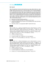
FCC Class B

/FCC B 级 /FCC B 級

FCC Class B

Note: This equipment has been tested and found to comply with the limits for a Class
B digital device, pursuant to part 15 of the FCC Rules. These limits are designed to
provide reasonable protection against harmful interference in a residential installa-
tion. This equipment generates, uses and can radiate radio frequency energy and, if
not installed and used in accordance with the instructions, may cause harmful inter-
ference to radio communications. However, there is no guarantee that interference
will not occur in a particular installation. If this equipment does cause harmful interfer-
ence to radio or television reception, which can be determined by turning the equip-
ment off and on, the user is encouraged to try to correct the interference by one or
more of the following measures: 

Reorient or relocate the receiving antenna. 

Increase the separation between the equipment and receiver. 

Connect the equipment into an outlet on a circuit different from that to which the 
receiver is connected. 

Consult the dealer or an experienced radio/TV technician for help.

FCC B 级

根据 FCC 规则第 15 款,本设备已经过检测并被判定符合 B 级数字设备标准。这些限制
旨在为居住环境下的系统操作提供合理保护,使其免受有害干扰。本设备会产生、使
用和发射无线电频率能量。如果没有按照手册说明正确安装和使用,可能对无线电通
讯造成有害干扰。但即使按照手册说明进行安装和使用,也并不能保证不会产生干扰。
若本设备会对无线电或电视信号接收产生有害干扰,用户可通过开、关设备进行确认。
当本设备产生有害干扰时,用户可采取下面的措施来解决干扰问题:

调整接收天线的方向或位置

增大本设备与接收器之间的距离

将本设备的电源接头插在与接收器使用不同电路的电源插座

若需技术支持,请咨询经销商或经验丰富的无线电 / 电视技术人员

FCC B 級
根據 FCC 規則第 15 款,本設備已經過檢測並被判定符合 B 級數位設備標準。這些限制
旨在為居住環境下的系統操作提供合理保護,使其免受有害干擾。本設備會產生、使
用和發射無線電頻率能量。如果沒有按照手冊說明正確安裝和使用,可能對無線電通
訊造成有害干擾。但即使按照手冊說明進行安裝和使用,也並不能保證不會產生干擾。
若本設備會對無線電或電視信號接收產生有害干擾,用戶可通過開、關設備進行確認。
當本設備產生有害干擾時,用戶可採取下面的措施來解決干擾問題:

調整接收天線的方向或位置

增大本設備與接收器之間的距離

將本設備的電源接頭插在與接收器使用不同電路的電源插座

若需技術支援,請諮詢經銷商或經驗豐富的無線電 / 電視技術人員

Summary of Contents for AIMB-B1000 Series

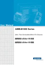
Page 1: ...User Manual AIMB B1000 Series Ultra Thin Embedded Mini ITX Chassis Mini ITX Mini ITX...

Page 2: ...any form or by any means without the prior written permission of Advantech Co Ltd Information provided in this manual is intended to be accurate and reliable How ever Advantech Co Ltd assumes no resp...

Page 3: ...ials service time and freight Please consult your dealer for more details If you think you have a defective product follow these steps 1 Collect all the information about the problem encountered For e...

Page 4: ...00 Two Bottom Mounting Brackets P N 1960014487T001 Four Bottom Rubber Foot P N 1990012452S000 Four M4 Screws for Bottom Rubber Foot Mounting Brackets P N 1930003238 Six Eight M3 Screws for Assembling...

Page 5: ...nclosure In order to protect the product from being damaged by ESD Electrostatic Discharge and EMI leakage we strongly recommend the use of CE compliant industrial enclo sure products CE ESD EMI CE CE...

Page 6: ...ter ference to radio communications However there is no guarantee that interference will not occur in a particular installation If this equipment does cause harmful interfer ence to radio or televisio...

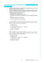
Page 7: ...ech s customer service center for technical support if you need additional assistance Please have the following information ready before you call Product name and serial number Description of your per...

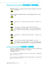
Page 8: ...e welcome comments and constructive criticism Please send all such in writing to support advantech com support advantech com support advantech com Warning Warnings if not observed indicate conditions...

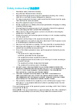
Page 9: ...e equipment For safety reasons the equipment should be opened only by qualified service personnel 14 If one of the following situations arises get the equipment checked by service personnel The power...

Page 10: ...AIMB B1000 User Manual x 1 2 3 4 5 6 7 8 9 10 11 12 13 14 15 20 C 4 F 60 C 140 F 16 17 UL 40 C IEC 704 1 1982 70dB A IEC 704 1 1 2 3 4 5 6 7 8 9 10 11 12 13 14...

Page 11: ...ura tion changes The sudden rush of power as you connect a jumper or install a card may damage sensitive electronic components 3 Electronic components are also vulnerable to damage by electrostatic di...

Page 12: ...AIMB B1000 User Manual xii...

Page 13: ...2 Installing the CPU Memory CPU CPU 6 2 3 Installing the HDD HDD HDD 7 Figure 2 3 Installing HDD HDD HDD 7 2 4 Installing the mini PCIe Device Memory of Bottom Side mini PCIe mini PCIe 7 Figure 2 4 Re...

Page 14: ...ploded Diagram AIMB B1201 AIMB B1201 12 Figure A 1 AIMB B1201 Exploded Diagram Parts List AIMB B1201 AIMB B1201 12 A 2 AIMB B1230 Exploded Diagram AIMB B1230 AIMB B1230 13 Figure A 2 AIMB B1230 Explod...

Page 15: ...Chapter 1 1 General Information...

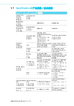
Page 16: ...emory 2 x 204 PIN DDR3 SODIMM Non ECC up to 16 GB 1333 1600 MHz SDRAM 2 x 204 PIN DDR3 SODIMM Non ECC up to 16 GB 1333 1600 MHz SDRAM Storage device 2 5 HDD bay 2 5 2 5 1 support 2 5 HDD SSD max 9 5 m...

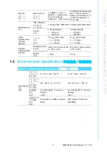
Page 17: ...ntrol 1 Power Button 1 1 1 Power Button 1 1 Power Requirements Voltage 19 VDC power input 19 VDC 19 VDC 12 VDC power input 12 VDC 12 VDC Physical Characteristics Dimensions W x H x D W x H x D 250 x 3...

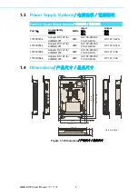
Page 18: ...C 100 240VAC 1 5A 50 60Hz DC 19V 3 42A 1757002944 Adapter DC 19V for AIMB B1201 90W AC 100 240VAC 1 5A 50 60Hz DC 19V 4 74A 1757003995 Adapter DC 12V for AIMB B1230 60W AC 100 240VAC 1 5A 50 60Hz DC 1...

Page 19: ...Chapter 2 2 System Setup and Maintenance...

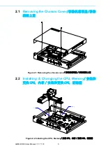
Page 20: ...AIMB B1000 User Manual 6 2 1 Removing the Chassis Cover Figure 2 1 Removing the chassis cover 2 2 Installing Changing the CPU Memory CPU CPU Figure 2 2 Installing the CPU Memory CPU CPU CPU Memory...

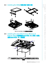
Page 21: ...lling the HDD HDD HDD Figure 2 3 Installing HDD HDD HDD 2 4 Installing the mini PCIe Device Memory of Bottom Side mini PCIe mini PCIe Figure 2 4 Removing the chassis cover and installing the mini PCIe...

Page 22: ...AIMB B1000 User Manual 8 2 5 Installing the Other Device Figure 2 5 Installing the antenna of wifi card Figure 2 6 Installing the CFast device CFast CFast...

Page 23: ...System Setup and Maintenance 2 6 Installing Bottom Mounting Brackets Rubber Foot Figure 2 7 Installing Bottom Mounting Brackets Rubber Foot 2 7 Installing the Power Cord Lock Harness Figure 2 8 Insta...

Page 24: ...AIMB B1000 User Manual 10...

Page 25: ...Appendix A A Exploded Diagram...

Page 26: ...MB B1201 AIMB B1201 Figure A 1 AIMB B1201 Exploded Diagram Parts List AIMB B1201 AIMB B1201 1 System Fan 6 HDD 2 Motherboard 7 HDD Holder 3 Bottom Chassis 8 Bottom Cover 4 Front Panel 9 Top Cover 5 Cf...

Page 27: ...B B1230 Exploded Diagram AIMB B1230 AIMB B1230 Figure A 2 AIMB B1230 Exploded Diagram Parts List AIMB B1230 AIMB B1230 1 System Fan 6 HDD 2 Motherboard 7 Bottom Cover 3 Bottom Chassis 8 Top Cover 4 Fr...

Page 28: ...e without notice No part of this publication may be reproduced in any form or by any means electronic photocopying recording or otherwise without prior written permis sion of the publisher All brand a...

Reviews: