background image

AIMB-C300 User Manual

II

Copyright

Advantech Co., Ltd copyrights this documentation and the software 
included with this product in 2005. All rights are reserved. Advantech 
Co., Ltd. reserves the right to make improvements in the products 
described in this manual at any time without notice. 
No part of this manual may be reproduced, copied, translated or transmit-
ted in any form or by any means without the prior written permission of 
Advantech Co., Ltd. Information provided in this manual is intended to 
be accurate and reliable. However, Advantech Co., Ltd. assumes no 
responsibility for its use, or for any infringements of the rights of third 
parties, which may result from its use.

Acknowledgements

IBM and PC are trademarks of International Business Machines Corpora-
tion.

On-line Technical Support

For technical support and service, please visit our support website at: 

http://www.advantech.com/support 

This manual is for the AIMB-C300.

 Part No. 2006C30001                                                                   2nd Edition,    
                                     

                                                      Nov.   2005 

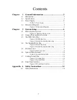
Summary of Contents for AIMB-C300

Page 1: ...AIMB C300 Multifunction Chassis for EmbATX motherboard User Manual...

Page 2: ...means without the prior written permission of Advantech Co Ltd Information provided in this manual is intended to be accurate and reliable However Advantech Co Ltd assumes no responsibility for its u...

Page 3: ...ements in part 15of the FCC rule Operation is subject to be following two conditions 1 this device may not cause harmful interference 2 this device must accept any interference received including inte...

Page 4: ...AIMB C300 User Manual IV...

Page 5: ...The HDD Drive Bay 7 Figure 2 2 HDD drive bay 7 Figure 2 3 Install the standard drive bay 8 2 4 The Standard Drive Bay 8 Figure 2 4 Insert the drives 8 Figure 2 5 Install the standard drive bay 9 2 5 P...

Page 6: ...AIMB C300 User Manual VI...

Page 7: ...CHAPTER 1 General Information...

Page 8: ...tem reset system alarm reset and system power switch The viewable LED indicators on front door support alarm notification of system status This ultra compact 2U ATX M B form factor delivers rack spac...

Page 9: ...ave and 5 500 Hz 1 G rms ran dom Dimensions W x H x D 383 x 362 x 90 9mm Safety CE compliant C UL approved 1 3 Power Supply Table 1 1 Power Supply Model Name Watt Input Output Mini load Safety MTBF 17...

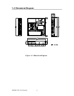
Page 10: ...AIMB C300 User Manual 4 1 4 Dimension Diagram Figure 1 1 Dimension Diagram...

Page 11: ...CHAPTER 2 System Setup...

Page 12: ...chassis To remove the top cover 1 Detach the two screws on the rear side 2 Lift off the cover IMPORTANT Make sure you fully remove the top cover when main taining full size cards Check all the power s...

Page 13: ...disk Installing disk drives 1 Remove the top cover 2 Detach the two screws holding the HDD bay 3 Lift off the HDD bay 4 Insert Hard Disks into their proper locations in the drive bay and secure them w...

Page 14: ...e power supply first it will easier to insert drive bay 3 Lift off the standard drive bay 4 Insert the drives into their proper locations in the drive bay and secure them with the screws provided plea...

Page 15: ...I riser card to the proper location with the provided two screws please refer to figure 2 6 2 64 bit PCI riser card First you have to take away the screw on the original location to avoid the riser ca...

Page 16: ...nance and provide adequate cooling to the system If one of those cooling fails please undo the two screws on the dual cooling fan holder Replace the failed cooling fan with a good one Please refer to...

Page 17: ...re used for system power and system reset Power On Off switch is used for switching the system on or off The Sys tem Reset switch re initializes the system This switch is similar to the hardware reset...

Page 18: ...AIMB C300 User Manual 12...

Page 19: ...Appendix A Safety Instructions...

Page 20: ...efore connecting the equipment to the power outlet 9 Position the power cord so that people cannot step on it Do not place anything over the power cord 10 All cautions and warnings on the equipment sh...

Page 21: ...ected to ACCESSIBLE METAL PARTS or other PROTECTIVELY EARTHED parts with a protective function to the PROTECTIVE EARTH TERMINAL shall be identified by the colors green and yellow at the termination of...

Page 22: ...AIMB C300 User Manual 16...

Reviews: