17
ARK-1380 User Manual
Chapter 2
H
/W Installation
2.5
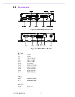
ARK-1380 Rear Side External I/O Connectors
2.5.1
Power ON/OFF Button
The ARK-1380 comes with a Power On/Off button, that support a dual function of
Soft Power -On/Off (Instant off or Delay 4 Second), and Suspend.
2.5.2
LED Indicators
There are two LEDs on the ARK-1380 front metal face plate for indicating system sta-
tus: the PWR LED for power status which flashes in green; and the HDD LED for
hard disk and compact flash disk status which flashes in red.
2.5.3
LVDS Connector
The ARK-1380 comes with a D-Sub 26-pin connector that carries LVDS signal out-
put, and can direct connect to an LVDS LCD Display via external cable.
The system also provides a jumper, CN14, on the internal motherboard for selecting
the LCD signal power of 5 V or 3.3 V. Please refer to section 2.1.2 for the CN14
jumper table, and Chapter 6, “Full Disassembly Procedure” to set it. Up. The default
setting of the CN14 is 5 V.
Figure 2.7 LVDS Connector
2.5.4
PCMCIA Expansion Slot
The ARK-1380 comes with a PCMCIA slot for PC card expansion.
Table 2.5: LVDS Connector Pin Assignment
Pin
Signal Name
Pin
Signal name
1
CLK2P
14
CLK2M
2
GND
15
A0M
3
A0P
16
A1M
4
A1P
17
A2M
5
A2P
18
CLK1M
6
CLK1P
19
GND
7
VCC_LCD
20
VDD_LCD
8
GND
21
A3M
9
A3P
22
A4M
10
A4P
23
A5M
11
A5P
24
A6M
12
A6P
25
A7M
13
A7P
26
GND
Summary of Contents for ARK-1380
Page 15: ...Chapter 2 2 H W Installation ...
Page 27: ...Chapter 3 3 BIOS Operation ...
Page 38: ...ARK 1380 User Manual 32 ...
Page 39: ...Chapter 4 4 Full Disassembly Procedure ...
Page 46: ...ARK 1380 User Manual 40 ...
Page 47: ...Appendix A A Intel Boot Agent Setup Menu ...
Page 49: ...43 ARK 1380 User Manual Appendix A Intel Boot Agent Setup Menu ...


