background image

63

ASMB-586 User Manual

Chapter 3

B

IOS Operation

3.3.10

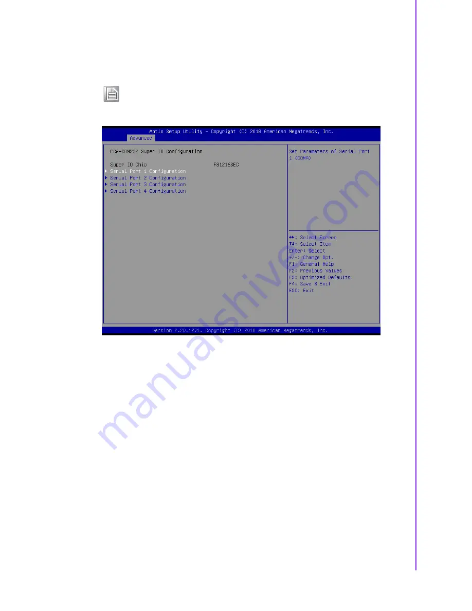
PCA-COM232/COM485 Super IO Configuration

Figure 3.13 Optional PCA-COM configuration screen

ASMB-586 offers extra four COM ports through LPC connector. You need to pur-
chase "PCA-COM232-00A1E" or "PCA-COM485-00A1E" then install it in the LPC
connector.

Note!

(This item only shows when a PCA COM module is installed)

Summary of Contents for ASMB-586

Page 1: ...User Manual ASMB 586 LGA 1151 Intel Xeon E and 8th Gen Core i3 i5 i7 series Micro ATX Server Board with 4 PCIe 6 USB 3 1 8 SATA3 Quad Dual LANs IPMI ...

Page 2: ...he prior written permission of Advantech Co Ltd Information provided in this manual is intended to be accurate and reliable How ever Advantech Co Ltd assumes no responsibility for its use nor for any infringe ments of the rights of third parties which may result from its use Acknowledgements AMI is a trademark of American Megatrends Inc IBM and PC are trademarks of International Business Machines ...

Page 3: ...t the maximum performance from your products So if you run into technical difficulties we are here to help For the most frequently asked questions you can easily find answers in your product documentation These answers are nor mally a lot more detailed than the ones we can give over the phone So please consult this manual first If you still cannot find the answer gather all the information or ques...

Page 4: ...radio frequency energy and if not installed and used in accordance with the instruction manual may cause harmful interference to radio communications Opera tion of this device in a residential area is likely to cause harmful interference in which case the user will be required to correct the interference at his her own expense The user is advised that any equipment changes or modifications not exp...

Page 5: ...r Information Part Number Chipset Memory LAN Display IPMI ASMB 586G4 00A1 C246 DDR4 288 pin ECC Non ECC unbuffered DIMM 4 DVI HDMI VGA Optional ASMB 586G2 00A1 C246 DDR4 288 pin ECC Non ECC unbuffered DIMM 2 DVI HDMI VGA Optional ...

Page 6: ...formation readily available 3 If your product is diagnosed as defective obtain an RMA return merchandise authorization number from your dealer This allows us to process your return more quickly 4 Carefully pack the defective product a fully completed Repair and Replacement Order Card and a photocopy proof of purchase date such as your sales receipt in a shippable container A product returned witho...

Page 7: ...ings 10 1 8 1 How to set jumpers 10 Table 1 5 CMOS clear JCMOS1 10 Table 1 6 ME update JME1 11 Table 1 7 Watchdog timer output JWDT1 11 Table 1 8 USB power switch JUSB1 JUSB2 12 Table 1 9 Fan mode selection CPUFAN_SEL1 SYSFAN_SEL1 12 Table 1 10 ATX AT mode selector PSON1 13 Table 1 11 PCIEX16_Slot6 link switch JPEG2 JPEG1 13 1 9 System Memory 14 Chapter 2 Connecting Peripherals 15 2 1 Introduction...

Page 8: ...figuration 48 Figure 3 7 PCH FW configuration screen 48 3 3 5 Trusted Computing 55 Figure 3 8 TPM settings screen 55 3 3 6 ACPI Settings 56 Figure 3 9 ACPI settings screen 56 3 3 7 SMART Settings 57 Figure 3 10SMART settings screen 57 3 3 8 Super IO Configuration 58 Figure 3 11Super IO configuration screen 58 3 3 9 NCT6776 HW Monitor 60 Figure 3 12PC health status screen 60 3 3 10 PCA COM232 COM48...

Page 9: ...Intel ME 107 4 2 6 SATA RAID 108 Appendix A Programming the Watchdog Timer109 A 1 Watchdog Timer Overview 110 A 2 Programming the Watchdog Timer 110 Table A 1 Watchdog timer registers 112 A 2 1 Example Programs 112 Appendix B I O Pin Assignments 117 B 1 USB2 0 Header USB7 12 118 Table B 1 USB2 0 Header USB7 12 118 B 2 USB3 1 Header USB5_6 118 Table B 2 USB 3 1 Header USB5_6 118 B 3 VGA Connector V...

Page 10: ...e Open Connector JCASE1 123 Table B 15 Case Open Connector JCASE1 123 B 16 Front Panel LAN LED Connector LAN_LED1 123 Table B 16 LAN LED Connector LANLED1 123 B 17 SPI Flash Card Pin Connector SPI_CN1 124 Table B 17 SPI Flash Connector SPI_CN1 124 B 18 GPIO Connector GPIO1 124 Table B 18 GPIO Connector GPIO1 124 B 19 SMBUS Connector SMBUS1 124 Table B 19 SMBUS Connector SMBUS1 124 B 20 PMBUS Conne...

Page 11: ...Chapter 1 1 Hardware Configuration ...

Page 12: ...applications 1 2 Features Triple Display One VGA DVI D and HDMI port can be used to implement tri ple display outputs PCIe architecture One PCIe x16 slot x16 link two x4 and one x1 slots from Intel C246 PCH High Performance I O capability Quad or dual Gigabit LAN via PCIe bus six USB 3 1 four Gen2 two Gen1 and seven USB 2 0 including one Type A 2 0 ports eight SATA III connectors Standard Micro AT...

Page 13: ... RS 232 PS 2 Keyboard and mouse connector To save rear I O space ASMB 586 reserve a 6 pins header on board KBMS1 and via a cable kit to build two 6 pin mini DIN connectors for easy connection to PS 2 keyboard and mouse USB port Supports up to six USB 3 1 ports four Gen2 ports in rear IO with transmission up to 10Gbps and seven USB 2 0 ports onboard with transmission rates up to 480 Mbps LPC One LP...

Page 14: ...19 LM LAN2 4 Intel I210 AT LAN2 is BMC shared NIC when the optional IPMI 1000 module is installed LAN3 4 is for G4 SKU only 1 3 7 Industrial Features Watchdog timer can generate a system reset or NC The watchdog timer is programmable with each unit equal to one second or minute 255 levels IPMI Supports IPMI 2 0 via optional IPMI 1000 module P N IPMI 1000 00A2E 1 3 8 Mechanical and Environmental Sp...

Page 15: ...onnecting external devices to your motherboard Table 1 1 Jumper list Label Function CPUFAN_SEL1 SYSFAN_SEL1 FAN PWM 1 2 DC mode 2 3 HDMI_I2C1 For RD debug purpose JCASE1 Case open JCMOS1 CMOS clear JME1 Intel ME disable jumper for ME BIOS update JPEG1 JPEG2 PCIEX16_SLOT6 PCIe link switch between x16 or x8x8 or x8x4x4 for riser card JPEG3 Default 1 2 reserve for debug 2 3 JTHR_SEL1 To select on boa...

Page 16: ...rd and mouse connector 6 pin LAN1_USB1_2 LAN2_USB3_4 LAN1 USB 3 1 Gen2 port 1 2 stack connector LAN2 USB 3 1 Gen2 port 3 4 stack connector LAN3_4 LAN3 LAN4 connector LANLED1 LAN LED extension connector LPC1 Low pin count connector for Advantech TPM and RS 232 422 485 modules PCIEX4_SLOT4 PCIe x4 slot Gen3 x4 link PCIEX1_SLOT5 PCIe x1 slot Gen3 x1 link PCIEX16_SLOT6 PCIe x16 slot Gen3 x16 link PCIE...

Page 17: ... PMBUS1 BMC1 DIMM A0 LAN1_ USB1_2 AUDIO1_2 PCIEX4_SLOT4 PCIEX1_SLOT5 PCIEX16_SLOT6 PCIEX4_SLOT7 COM1 DIMM A1 DIMM B0 DIMM B1 ATX12V1 FDAUD1 USB11_12 USB7_8 ATXPWR1 VOLT1 SYSFAN _SEL1 JWDT1 CPUFAN_SEL1 EX_THR1 JTHR_SEL1 JPEG1 2 SYS_LED1 SYSFAN2 SYSFAN1 SYSFAN0 LAN_LED1 GPIO1 SGPIO1 2 JFP1 JFP2 JFP3 SMBUS1 LPC1 PSON1 SPI_CN1 SATA0 7 JUSB2 JCASE1 JME1 SPDIF_OUT1 SYSFAN3 CPUFAN0 BAT2 SPI4 JUSB1 Onboar...

Page 18: ... 100 Mbps Link Active Amber Amber Green Blinking green Green Blinking green Amber Amber 1000 Mbps Link Active Green Green Green Blinking green Green Blinking green Green Green No Link Off Off Off Off Table 1 4 Onboard LED LED2 LED3 LED4 LED Description LED Definition 5V_LED2 Power on LED Off Power off On Green System is On 5VSB_LED3 Standby LED Off No input AC Power On Green System is ON in sleep ...

Page 19: ...erter VGA D Sub 8 x SATA3 RAID 0 1 5 10 USB 2 0 7 x USB2 0 USB 3 1 6 x USB3 1 Warning Always completely disconnect the power cord from your chassis when ever you work with the hardware Do not make connections while the power is on Sensitive electronic components can be damaged by sud den power surges Only experienced electronics personnel should open the PC chassis Caution Always ground yourself t...

Page 20: ...nnect the pins with the clip To open or turn off a jumper you remove the clip Sometimes a jumper consists of a set of three pins labeled 1 2 and 3 In this case you connect either pins 1 and 2 or 2 and 3 A pair of needle nose pliers may be useful when set ting jumpers 1 8 1 1 CMOS clear JCMOS1 The ASMB 586 motherboard contains a jumper that can erase CMOS data and reset the system BIOS information ...

Page 21: ...reset the CPU This feature means the ASMB 586 will recover from a software failure or an EMI problem The JWDT1 jumper settings controls the outcome of what the computer will do in the event the watchdog timer is tripped Table 1 6 ME update JME1 Function Jumper Setting Lock ME update ME update default setting 1 2 closed 1 2 3 2 3 closed 1 2 3 Table 1 7 Watchdog timer output JWDT1 Function Jumper Se...

Page 22: ...hed to 5V If you want to disable USB stand by power under S5 and under 2 3 closed it won t support S3 and S4 modes 1 8 1 5 CPU SYSTEM fan PWM DC mode selection CPUFAN_SEL1 SYSFAN_SEL1 The ASMB 586 contains a jumper that can support PWM or DC mode Normally this jumper should be set with pin 1 2 closed If you want to change to DC mode set CPUFAN_SEL1 SYSFAN_SEL1 to 2 3 closed to disable it Table 1 8...

Page 23: ...6_SLOT6 to two PCIe x8 link or one PCIe x8 two PCIe x4 link Default set ting with pin 1 2 closed is one x16 on PCIEX16_SLOT6 For jumper settings for riser card support please refer to Section 2 14 PCIe x16 Expansion Slot Table 1 10 ATX AT mode selector PSON1 Function Jumper Setting AT Mode ATX Mode default setting 1 2 3 1 2 closed 2 3 closed 1 2 3 Table 1 11 PCIEX16_Slot6 link switch JPEG2 JPEG1 F...

Page 24: ...System Memory ASMB 586 has four 288 pin memory sockets for unbuffered ECC Non ECC 2666 2400 2133 MHz memory modules with maximum capacity of 64 GB Maximum 16 GB for each DIMM Note ASMB 586 does NOT support registered DIMMs RDIMMs ...

Page 25: ...Chapter 2 2 Connecting Peripherals ...

Page 26: ...upport trans mission rates up to 10Gbps and USB5 6 are USB 3 1 Gen1 ports with transmission rates up to 5Gbps These ports support Plug Play and hot swapping for up to 127 external devices and are able to be disabled in BIOS menu The ASMB 586 is equipped with two G2 SKU or four G4 SKU high performance 1000 Mbps Ethernet LANs They are supported by all major network operating sys tems The RJ 45 jacks...

Page 27: ...r is set as 5V the board doesn t support S3 S4 Refer to Section 1 8 1 4 for details of jumper settings Jumper Function JUSB1 Rear window USB3 1 Gen2 port power source switch between 5 VSB and 5 V JUSB2 On board USB2 0 3 1 Gen1 port power source switch between 5 VSB and 5 V Note When USB power is switched to 5V it cannot be connected to a pow ered KVM JUSB1 JUSB2 ...

Page 28: ...er Manual 18 2 4 Display Connector HDMI1_VGA1 DVI1 The ASMB 586 is equipped with VGA DVI D and HDMI connectors for triple display output However results may differ because of OS support limitations HDMI1_VGA1 DVI1 ...

Page 29: ...d However if you want to disable the port or change these parameters later you can do this in the system BIOS setup Different devices implement the RS 232 standards in different ways Up to eight COM ports may appear in Windows Devices Managers when all devices are enabled Besides COM1 and COM2 for RS 232 COM3 is reserved as a virtual COM port for Linux OS users COM4 is for Intel AMT or IPMI SOL su...

Page 30: ...n onboard external keyboard and mouse connector on the motherboard This gives system integrators greater flexibility in designing their systems A KBMS cable and cable bracket installed in the rear of system are provided as optional P N 1700019268 11 1960063434N000 KBMS1 ...

Page 31: ...21 ASMB 586 User Manual Chapter 2 Connecting Peripherals 2 7 CPU Fan Connector CPUFAN0 If a fan is used this connector supports cooling fans that draw up to 2 5A 30W CPUFAN0 ...

Page 32: ...ASMB 586 User Manual 22 2 8 System FAN Connector SYSFAN0 SYSFAN3 If a fan is used this connector supports cooling fans that draw up to 2 5A 30W SYSFAN3 SYSFAN2 SYSFAN1 SYSFAN0 ...

Page 33: ...rals 2 9 Front Panel Connectors JFP1 2 3 There are several external switches and LEDs to monitor and control ASMB 586 JFP3 JFP1 JFP2 3 6 9 12 2 5 8 11 PWRSW RESET HDDLED SNMP JFP1 2 5 8 11 1 4 7 10 HDDLED SM_BUS SPEAKER JPF2 PWRLED KEYLOCK 1 2 3 4 5 JFP3 ...

Page 34: ...n the HDD is active 2 9 4 SNMP SMBus Connector JFP2 pins 8 11 ASMB 586 supports Advantech Intelligent System Module for providing a platform independent system management When you re installing a module on ASMB 586 connect it to pins 8 and 11 on JFP2 Pin 8 is a data pin pin 11 is a clock pin 2 9 5 ATX Soft Power Switch JFP1 pins 3 6 If your computer case is equipped with an ATX power supply you sh...

Page 35: ... Connecting Peripherals 2 10 Alarm Board Connector VOLT1 VOLT1 connects to the alarm board of Advantech chassis This alarm board monitors the input voltage of 12V 5V 5Vsb 5V 3 3V and 12V and give warnings if a power supply fails VOLT1 ...

Page 36: ...isabled in the BIOS Before using please remove the jumper and attach the appropriate cable from the chassis Then change the BIOS setting to enable the case open function Refer to the chapter of HW Monitor in BIOS setting If the chassis is opened the BIOS will inform you with a warning message of a chassis intrusion during system reboot and post screen JCASE1 ...

Page 37: ...27 ASMB 586 User Manual Chapter 2 Connecting Peripherals 2 12 Front Panel LAN Indicator Connector LANLED1 LANLED1 is extension connector of LAN1 LAN4 LAN1_LED1 ...

Page 38: ... 7 ASMB 586 features eight high performance serial ATA III interfaces up to 600 MB s for massive storage applications Software RAID 0 1 10 5 can be supported with Intel RSTe Rapid Storage Technology Enterprise SATA6 SATA7 SATA0 SATA3 SATA1 SATA4 SATA2 SATA5 ...

Page 39: ...heir applications require higher graphics performance than the CPU embedded graphics controller can provide or high bandwidth demanded I O card such as frame grabber card raid card and 10G LAN card Note Some legacy cards may be incompatible under Windows 10 when CSM configuration in BIOS is set to legacy from the default UEFI mode Please contact FAE for technical support on this PCIEX16_SLOT6 ...

Page 40: ...E PCIe x8 x8 2U ASMB RF3X8 21A1E ASMB RF348 21A1E ASMB RF388 21A1E PCIe x8 x4 x4 2U ASMB RF388 21A1E default setting Note When installing ASMB RF348 21A1E riser card and setting PCIe x16 slot as x8 x8 mode it supports one PCIe x4 bottom slot and one PCIe x8 top slot The middle PCIe x4 of riser card won t work 1 2 closed 1 2 3 1 2 closed 1 2 3 2 3 closed 1 2 3 1 2 closed 1 2 3 2 3 closed 1 2 3 2 3 ...

Page 41: ...rals 2 15 PCIe x4 x1 Expansion Slot PCIEX4_SLOT4 7 PCIEX1_SLOT5 PCIEX4_SLOT4 and PCIEX4_SLOT7 are in Gen3 x4 link speed PCIEX1_SLOT1 is Gen3 x1 link Higher speed cards have speed downgrades when used in these slots PCIEX4_SLOT4 PCIEX1_SLOT5 PCIEX4_SLOT7 ...

Page 42: ...configured system we rec ommend that you use a power supply unit PSU that complies with ATX 12V Specifi cation 2 0 or later version Do not forget to connect the 8 pin power plug or through 4 pin to 8 pin converted cable P N 1700019748 when there s no 8 pin power plug on the PSU otherwise the system will not boot ATX12V1 ...

Page 43: ...33 ASMB 586 User Manual Chapter 2 Connecting Peripherals 2 17 SPI Flash Connector SPI_CN1 SPI flash programmer pin header for RMA can flash BIOS while ASMB 586 is not be powered on SPI_CN1 ...

Page 44: ...86 is reserved for Advantech TPM and COM RS 232 422 485 modules Advantech P N LPC Module PCA TPM 00A1E PCA TPM 00B1E TPM 1 2 module TPM 2 0 module PCA COM232 00A1E 4 ports RS 232 module connect to LPC connector PCA COM485 00A1E 4 ports RS 422 485 module connect to LPC connector LPC1 ...

Page 45: ...hapter 2 Connecting Peripherals 2 19 PMBUS Connector PMBUS1 PMBUS connector on ASMB 586 is reserved for communication with power supply via BMC The IPMI module P N IPMI 1000 00A2E must be installed to enable this feature PMBUS1 ...

Page 46: ...ASMB 586 User Manual 36 ...

Page 47: ...Chapter 3 3 BIOS Operation ...

Page 48: ...r of menus for making changes and turning the special features on or off This chapter describes the basic navigation of the ASMB 586 setup screens Figure 3 1 Main setup screen AMI s BIOS ROM has a built in Setup program that allows users to modify the basic system configuration This information is stored in NVRAM area so it retains the Setup information when the power is turned off ...

Page 49: ... the screen Use arrow keys to select among the items and press Enter to accept or enter the sub menu Figure 3 2 Main setup screen The Main BIOS setup screen has two main frames The left frame displays all the options that can be configured Grayed out options cannot be configured options in blue can be The right frame displays the key legend Above the key legend is an area reserved for a text messa...

Page 50: ...n the left frame of the screen such as CPU configuration to go to the sub menu for that item You can display an Advanced BIOS Setup option by highlighting it using the Arrow keys All Advanced BIOS Setup options are described in this section The Advanced BIOS Setup screens are shown below The sub menus are described on the following pages Figure 3 3 Advanced BIOS features setup screen ...

Page 51: ...sc Configuration Figure 3 4 Platform misc configuration screen Native PCIE Enable Enable Disable PCIe native control When changed to enable Native ASPM can be selected as Enabled for OS control and ASPM or Disabled for BIOS control Default is disable for BIOS control ...

Page 52: ...ardware Prefetcher To turn on off the MLC streamer prefetcher Hardware Prefetcher is a technique that fetches instructions and or data from memory into the CPU cache memory well before the CPU needs it so that it can improve the load to use latency You may choose to enable or disable it ...

Page 53: ...Line Prefetch mechanism like automatic hardware prefetch operates without programmer intervention When enabled through the BIOS two 64 byte cache lines are fetched into a 128 byte sector regardless of whether the additional cache line has been requested or not You may choose to enable or disable it ...

Page 54: ... disable the Intel Virtualization Technology IVT extension It allows multiple operating systems to run simultaneously on the same system It does this by creating virtual machines each running its own x86 operating system Active Processor Cores Number of cores to enable in each processor package ...

Page 55: ... Hyper Threading Enable or disable a Hyper Threading processor to optimize as two logical pro cessors allowing the OS to schedule two threads or processors simultaneously AES This item enables or disables CPU advanced encryption standard instructions ...

Page 56: ...Power Performance Figure 3 6 CPU power management control screen Boot performance mode Select the performance state that the BIOS will set before OS handoff Intel R SpeedStep tm Allows more than two frequency ranges to be supported ...

Page 57: ...3 BIOS Operation Turbo Mode Enable Disable processor turbo mode requires Intel Speed Step or Intel Speed Shift to be available and enabled C States Enable Disable CPU power management Allows CPU to go to C states when not 100 utilized ...

Page 58: ...ASMB 586 User Manual 48 3 3 4 PCH FW Configuration Figure 3 7 PCH FW configuration screen This page shows the Intel ME configuration ...

Page 59: ...B 586 User Manual Chapter 3 BIOS Operation 3 3 4 1 AMT Configuration ASF support Enable Disable alert standard format support USB Provisioning of AMT Enable Disable of AMT USB provisioning CIRA Configuration ...

Page 60: ...ASMB 586 User Manual 50 Activate Remote Assistance Process Trigger CIRA boot Network access must be activated first from MEBx setup ASF Configuration ...

Page 61: ...ive PET events WatchDog Enable or disable WatchDog Timer ASF Sensors Table Adds ASF Sensor Table into ASF ACPI Table Secure Erase Configuration Secure Erase mode Change Secure Erase module behavior to Simulated or Rear Force Secure Erase Enable or disable Force Secure Erase on next boot OEM Flags Settings ...

Page 62: ...tion screens Press 2 to initiate a remote connection Network Access must be activated from MEBx Setup for this screen to be displayed Hide Unconfigure ME Confirmation Prompt Hide Unconfigure ME Confirmation Prompt when attempting ME unconfigu ration MEBx OEM Debug Menu Enable Enable OEM debug menu in MEBx Unconfigure ME Unconfigure ME with resetting MEBx password to default ...

Page 63: ...er Manual Chapter 3 BIOS Operation MEBx Resolution Settings Non UI Mode Resolution Resolution for non UI text mode UI Mode Resolution Resolution for UI text mode Graphics Mode Resolution Resolution for graphics mode ...

Page 64: ...ASMB 586 User Manual 54 3 3 4 2 Firmware Update Configuration Me FW Image Re Flash Enable Disable Me FW image re flash function ...

Page 65: ...6 User Manual Chapter 3 BIOS Operation 3 3 5 Trusted Computing Figure 3 8 TPM settings screen Security Device Support Enable or disable TPM support You can purchase Advantech LPC TPM module to enable TPM function ...

Page 66: ...CPI Auto Configuration Enable Hibernation Enable or disable Hibernate OS S4 Sleep State that may not be effective with some operating systems ACPI Sleep State Specifies the ACPI sleep state when the system enters suspend Lock Legacy Resources Enable or disable Lock Legacy Resources S3 Video Repost Enable or disable S3 video repost ...

Page 67: ...57 ASMB 586 User Manual Chapter 3 BIOS Operation 3 3 7 SMART Settings Figure 3 10 SMART settings screen SMART Self Test Enable or disable SMART self test on all HDDs during post ...

Page 68: ...anual 58 3 3 8 Super IO Configuration Figure 3 11 Super IO configuration screen Serial Port 1 Configuration Serial Port Enable or disable Serial Port COM1 Change Settings Select an optimal settings for Super IO Device ...

Page 69: ...59 ASMB 586 User Manual Chapter 3 BIOS Operation Serial Port 2 Configuration Serial Port Enable or disable Serial Port COM2 Change Settings Select an optimal setting for Super IO Device ...

Page 70: ...ASMB 586 User Manual 60 3 3 9 NCT6776 HW Monitor Figure 3 12 PC health status screen ...

Page 71: ...it correctly to run this function Watch Dog Timer Enable Disable Watch Dog Timer function CPU Warning Temperature Use this to set the CPU warning temperature threshold When the system reaches the warning temperature the speaker will beep ACPI Shutdown Temperature Use this to set the ACPI shutdown temperature threshold When the system reaches the shutdown temperature it will be automatically shut d...

Page 72: ...rt Fan Function ASMB 586 offers three different fan modes 1 Normal Mode Enable smart fan for normal system configuration 2 Quiet Mode Enable smart fan for quiet system with no expansion cards 3 Disable All fans run at full speed ...

Page 73: ...IO Configuration Figure 3 13 Optional PCA COM configuration screen ASMB 586 offers extra four COM ports through LPC connector You need to pur chase PCA COM232 00A1E or PCA COM485 00A1E then install it in the LPC connector Note This item only shows when a PCA COM module is installed ...

Page 74: ...ASMB 586 User Manual 64 Serial Port 1 Configuration Serial Port Enable or Disable Serial Port 1 Change Settings Select resource allocation for Serial Port 1 ...

Page 75: ...rt Enable or Disable Serial Port 3 Change Settings Select resource allocation for Serial Port 3 Serial Port 4 Configuration Serial Port Enable or Disable Serial Port 4 Change Settings Select resource allocation for Serial Port 4 3 3 11 S5 RTC Wake Settings Figure 3 14 S5 RTC wake settings screen Wake system from S5 Enable Disable system wake on alarm event Select fixed time system will wake on the...

Page 76: ...ASMB 586 User Manual 66 3 3 12 Serial Port Console Redirection Figure 3 15 Serial port console redirection screen Console Redirection Enable or disable the console redirection feature ...

Page 77: ...67 ASMB 586 User Manual Chapter 3 BIOS Operation Legacy Console Redirection Settings ...

Page 78: ...ASMB 586 User Manual 68 ...

Page 79: ...solution On Legacy OS the Number of Rows and Columns supported redirection Redirect After POST When Bootloader is selected then Legacy Console Redirection is disabled before booting to legacy OS When Always Enable is selected then Leg acy Console Redirection is enabled for legacy OS 3 3 13 Intel TXT Information Figure 3 16 Intel TXT information screen ...

Page 80: ... PCI subsystem settings screen Hot Plug Support Enable or disable Hot Plug capable slots Default is set to Enabled Provides a setup screen for selecting PCI resource padding for Hot Plug Note Changing PCI Device settings may have unwanted side effects System may hang ...

Page 81: ...ble option will keep USB devices available only for EFI applications This option is valid after BIOS is set to Legacy from the default UEFI mode XHCI Hand off This is a workaround for OS without XHCI hand off support The XHCI owner ship change should be claimed by XHCI driver USB Mass Storage Driver Support Enable or disable USB Mass Storage Driver Support USB transfer time out The time out value ...

Page 82: ...rage device Start Unit command time out Device power up delay Maximum time the device will take before it properly reports itself to the Host Controller Auto uses default value for a Root port it is 100 ms for a Hub port the delay is taken from Hub descriptor ...

Page 83: ...r 3 BIOS Operation Mass Storage Devices Mass storage device emulation type Auto enumerates devices according to their media format Optical drives are emulated as CDROM drives with no media will be emulated according to a drive type ...

Page 84: ...ASMB 586 User Manual 74 ...

Page 85: ...Network Stack Configuration Figure 3 19 UEFI network stack configuration screen UEFI Network Stack Enable or Disable UEFI Network Stack IPv4 IPv6 PXE Support Enable or Disable IPv4 IPv6 PXE boot support If disabled IPv4 IPv6 PXE boot support will not be available ...

Page 86: ...al 76 PXE boot wait time Wait time in seconds to press ESC key to abort the PXE boot Media detect count Number of times the presence of media will be checked 3 3 17 CSM Configuration Figure 3 20 CSM configuration screen ...

Page 87: ...When disabled system can only support UEFI mode GateA20 Active This items is useful when RT code is executed above 1MB When it s set as Upon Request GA20 can be disabled using BIOS services When it s set as Always it does not allow disabling of GA20 Option ROM Messages Force BIOS or Keep Current to set the display mode for Option ROM ...

Page 88: ...BIOS reaction on INT19 trapping by Option ROM When it s set as Immediate the trap will be executed right away When it s set as Postponed the trap will be executed during legacy boot HDD Connection Order Some OS require HDD handles to be adjusted ...

Page 89: ...79 ASMB 586 User Manual Chapter 3 BIOS Operation Boot option filter This option controls Legacy UEFI ROMs priority Option ROM execution Network Controls the execution of UEFI and Legacy PXE OpROM ...

Page 90: ...ASMB 586 User Manual 80 Storage Controls the execution of UEFI and Legacy Storage OpROM Video Controls the execution of UEFI and Legacy Video OpROM ...

Page 91: ...81 ASMB 586 User Manual Chapter 3 BIOS Operation Other PCI devices Determines execution of OpROM policy for devices other than Network Storage or Video ...

Page 92: ...ASMB 586 User Manual 82 3 4 Chipset Figure 3 21 Chipset screen 3 4 1 System Agent SA Configuration Figure 3 22 System agent SA configuration screen VT d ...

Page 93: ...ssignment This is disabled automatically when the size is set to 2048MB 3 4 1 1 Memory Configuration Maximum Memory Frequency Maximum Memory Frequency selections in Mhz Valid values should match the refclk e g divide by 133 or 100 Max TOLUD Maximum Value of TOLUD Dynamic assignment would adjust TOLUD automat ically based on largest MMIO length of installed add on cards ...

Page 94: ...lay Select Auto IGFX PEG PCI Graphics device as primary display External Gfx Card Primary Display Configuration Select PEG0 PEG1 PEG2 PEG3 Graphics device as Primary PEG This option is unnecessary to change since ASMB 586 only has one PCIe Slot 6 for exter nal Gfx card ...

Page 95: ...85 ASMB 586 User Manual Chapter 3 BIOS Operation Internal Graphics Keep IGFX enabled based on the setup options ...

Page 96: ...deo device which will be activated during POST This has no effect if external graphics are present Secondary boot display selection will appear based on your selection VGA mode will be supported only on primary display 3 4 1 3 PCIe SLOT6 Configuration ...

Page 97: ...ed Configure PEG 0 1 0 Max Speed PCIe SLOT6 ROOT PORT1 Enable Root Port Auto Disabled Enabled Max Link Speed Configure PEG 0 1 1 Max Speed PCIe SLOT6 ROOT PORT2 Enable Root Port Auto Disabled Enabled Max Link Speed Configure PEG 0 1 2 Max Speed PEG Port Feature Configuration Detect Non Compliance PCI Express Device in PEG ...

Page 98: ...ASMB 586 User Manual 88 3 4 2 PCH IO Configuration Figure 3 23 PCH IO configuration screen ...

Page 99: ...tion ROM Enable or disable Boot Options for LAN4 controller PCIE Wake Enable or disable PCIE to wake the system from S5 PowerOn by Modem Enable or disable PowerOn by Modem Deep Sleep Enable or disable Deep Sleep support Restore AC Power Loss Select what state to go to when power is re applied after a power failure G3 state Note When a system enters G3 status with deep S5 enabled some power supply ...

Page 100: ...ASMB 586 User Manual 90 3 4 2 1 PCI Express Configuration Figure 3 24 PCI Express configuration screen ...

Page 101: ... the PCI Express Root Port Advanced Error Reporting Enable or disable advanced error reporting It may occur system BSOD problem when set to Enable but the PCIe card has no support Advanced Error Report ing AER function PCIe Speed Sets PCIe speed for PCI Express slots 4 5 7 ...

Page 102: ...oller Speed Indicates the maximum speed the SATA controller can support Port 0 7 Enable or disable SATA port 0 7 Hot Plug Designates this port as Hot Pluggable Spin Up Device If enabled for any ports Staggered Spin Up will be performed and only the drives which have this option enabled will spin up at boot Otherwise all drives spin up at boot SATA Device Type Identifies the SATA port is connected ...

Page 103: ...ter 3 BIOS Operation 3 4 2 3 USB Configuration Figure 3 26 USB configuration screen XHCI Disable Compliance Mode Enable or disable compliance mode Default is to disable Compliance Mode Change to enabled for Compliance Mode testing ...

Page 104: ...een RTC Memory Lock Enable will lock bytes 38h 3Fh in the lower upper 128 byte bank of RTC RaM BIOS Lock Enable or disable the PCH BIOS Lock Enable feature Enable to ensure SMM protection of flash Force unlock on all GPIO pads If enabled BIOS will force all GPIO pads to be in an unlocked state ...

Page 105: ...95 ASMB 586 User Manual Chapter 3 BIOS Operation 3 4 2 5 HD Audio Configuration Figure 3 28 HD Audio configuration screen HD Audio Controls detection of the HD Audio device ...

Page 106: ...9 Security screen Select Security Setup from the ASMB 586 setup main BIOS setup menu All Security Setup options such as password protection are described in this section To access the sub menu for the following items select the item and press Enter ...

Page 107: ...ey Bootup NumLock State On or Off power on state for the NumLock Quiet Boot If this option is set to Disabled the BIOS displays normal POST messages If Enabled an OEM logo is shown instead of POST messages Boot Option Priorities Choose boot priority from boot device Note UEFI devices can be recognized as default Set Enabled in CSM Con figuration to support legacy devices when needed ...

Page 108: ...em configuration select this option to save your changes exit BIOS setup and reboot into the computer so the new system con figuration parameters can take effect Discard Changes and Reset Select this option to quit setup and reset computer without making any perma nent changes to the system configuration Save Changes Select this option to save your changes Discard Changes Select this option to dis...

Page 109: ...option allows you to attempt to launch the EFI Shell application shellx64 efi from one of the available file system devices When you make some critical changes the system will still reboot even after you choose Save Changes and Exit 3 8 Server Mgmt Figure 3 32 Server Mgmt screen ...

Page 110: ...nse for specified time out BMC starts at the same time when BIOS starts during AC power ON It takes around 30 seconds to initialize Host to BMC interfaces with beep sound but without display output until initial ization is completed BMC Counter Note This item only shows when an IPMI module is installed P N IPMI 1000 00A2E ...

Page 111: ...101 ASMB 586 User Manual Chapter 3 BIOS Operation 3 8 1 System Event Log ...

Page 112: ...event logging for error progress codes during boot Erase SEL Choose options for erasing SEL When SEL is Full Choose options for reactions to a full SEL Log EFI Status Codes Disable the logging of EFI status codes or log only error code or progress code or both ...

Page 113: ...103 ASMB 586 User Manual Chapter 3 BIOS Operation 3 8 2 BMC Self Test Log Erase Log Erase log or not on every reset When Log is Full Clear log or do not log any more when log is full ...

Page 114: ...ion Configuration Address Source Select to configure LAN channel1 parameters statically or dynamically by BIOS or BMC Unspecified option will not modify any BMC network parameters dur ing BIOS phase ASMB 586 design has reserved LAN2 port as IPMI share NIC ...

Page 115: ...Chapter 4 4 Driver Installation ...

Page 116: ...Chipset Software Installation CSI utility installs the Windows INF files that outline to the operating system how the chipset components will be configured This is needed for the proper functioning of the following features Serial ATA interface support USB 1 1 2 0 3 1 support Identification of Intel chipset components in the Device Manager Note For system stability installing the drivers in the fo...

Page 117: ...thernet at 1000 Mbps Features include 10 100 1000 Mbps Ethernet controller 10 100 1000 Mbps triple speed MAC Full duplex at 10 100 or 1000 Mbps and half duplex at 10 or 100 Mbps Wake on LAN WOL support PCIe x1 host interface The integrated Intel gigabit Ethernet controller supports all major network operating systems However the installation procedure varies with different operating systems Contac...

Page 118: ...three or more hard drives where the data is divided into man ageable blocks called stripes Parity is a mathematical method for recreating data that was lost from a single drive which increases fault tolerance The data and parity are striped across all the hard drives in the array The parity is striped in a rotating sequence to reduce bottlenecks associated with the parity calculations RAID 10 arra...

Page 119: ...Appendix A A Programming the Watchdog Timer ...

Page 120: ... controller NCT6776 It provides the fol lowing functions for user programming Can be enabled and disabled by user s program Timer can be set from 1 to 255 sec min Generates an interrupt or resets signal if the software fails to reset the timer before time out A 2 Programming the Watchdog Timer The I O port address of the watchdog timer is 2E hex and 2F hex 2E hex is the address port 2F hex is the ...

Page 121: ...ASMB 586 User Manual Appendix A Programming the Watchdog Timer Unlock NCT6776 Select register of watchdog timer Enable the function of the watchdog timer Use the function of Lock NCT6776 the watchdog timer ...

Page 122: ... units for the timer Write 0 to bit 3 set seconds as counting unit default Write 1 to bit 3 set minutes as counting unit Write 1 to bit 4 Watchdog timer count mode is 1000 times faster If bit 3 is 0 the count mode is 1 1000 seconds mode If bit 3 is 1 the count mode is 1 1000 minutes mode F6 hex write 0 stop timer default 01 FF hex The amount of the count in seconds or minutes depends on the value ...

Page 123: ... al 10 10 minutes Out dx al Dec dx lock NCT6776 Mov al 0aah Out dx al Enable watchdog timer and set 5 minutes as the timeout interval Mov dx 2eh unlock NCT6776 Mov al 87h Out dx al Out dx al Mov al 07h Select registers of watchdog timer Out dx al Inc dx In al dx Or al 08h Out dx al Dec dx Enable the function of watchdog timer Mov al 30h Out dx al Inc dx Mov al 01h Out dx al Dec dx Set minute as co...

Page 124: ... Mov dx 2eh unlock NCT6776 Mov al 87h Out dx al Out dx al Mov al 07h Select registers of watchdog timer Out dx al Inc dx Mov al 08h Out dx al Dec dx Enable the function of watchdog timer Mov al 30h Out dx al Inc dx In al dx Or al 01h Out dx al Dec dx Enable watchdog timer to be reset by mouse Mov al 0f7h Out dx al Inc dx In al dx Or al 80h Out dx al Dec dx lock NCT6776 Mov al 0aah Out dx al Enable...

Page 125: ...ov al 30h Out dx al Inc dx Mov al 01h Out dx al Dec dx Enable watchdog timer to be strobed reset by keyboard Mov al 0f7h Out dx al Inc dx In al dx Or al 40h Out dx al Dec dx lock NCT6776 Mov al 0aah Out dx al Generate a time out signal without timer counting Mov dx 2eh unlock NCT6776 Mov al 87h Out dx al Out dx al Mov al 07h Select registers of watchdog timer Out dx al Inc dx Mov al 08h Out dx al ...

Page 126: ...ual 116 Out dx al Inc dx In al dx Or al 01h Out dx al Dec dx Generate a time out signal Mov al 0f7h Out dx al Write 1 to bit 5 of F7 register Inc dx In al dx Or al 20h Out dx al Dec dx lock NCT6776 Mov al 0aah Out dx al ...

Page 127: ...Appendix B B I O Pin Assignments ...

Page 128: ... 3 USB2_D1 4 USB2_D2 5 USB2_D1 6 USB2_D2 7 GND 8 GND 9 Key 10 N C 1 2 10 Table B 2 USB 3 1 Header USB5_6 Pin Signal Pin Signal 1 5V_USB 20 Key 2 USB3_RX_D1 19 5V_USB 3 USB3_RX_D1 18 USB3_RX_D2 4 GND 17 USB3_RX_D2 5 USB3_TX_D1 16 GND 6 USB3_TX_D1 15 USB3_TX_D2 7 GND 14 USB3_TX_D2 8 USB2_D1 13 GND 9 USB2_D1 12 USB2_D2 10 USB_OC 11 USB2_D2 19 11 1 10 ...

Page 129: ...face COM1 2 Table B 3 VGA Connector VGA1 Pin Signal Pin Signal 1 RED 9 VCC 2 GREEN 10 GND 3 BLUE 11 N C 4 N C 12 SDA 5 GND 13 H SYNC 6 GND 14 V SYNC 7 GND 15 SCL 8 GND 5 15 1 11 10 6 Table B 4 RS 232 Interface COM1 2 COM1 COM2 Pin Signal 1 DCD 2 DSR 3 RXD 4 RTS 5 TXD 6 CTS 7 DTR 8 RI 9 GND 1 2 9 ...

Page 130: ...ED and Keyboard Lock JFP3 Table B 5 External Keyboard and Mouse Connector KBMS1 Pin Signal 1 KB CLK 2 KB DATA 3 MS DATA 4 GND 5 VCC 6 MS CLK Table B 6 Fan Power Connector SYSFAN0 3 Pin Signal 1 GND 2 12 V 3 DETECT 4 PWM Table B 7 Power LED and Keyboard Lock JFP3 Pin Signal 1 LED power 3 3 V 2 NC 3 LED power 4 keylock 5 Ground ...

Page 131: ...HDD LED Connector JFP2 B 10 SNMP SMBus Connector JFP2 Table B 8 External Speaker Connector JFP2 Pin Signal 1 SPK_VCC 4 SPK_OBS 7 SPK_BUZ 10 SPK_OUT 1 4 7 10 Table B 9 HDD LED Connector JFP2 Pin Signal 2 HDD_LED 5 HDD_LED 2 5 Table B 10 SNMP SMBus Connector JFP2 Pin Signal 8 HWM_SDA 11 HWM_SCL 8 11 ...

Page 132: ...ector FPAUD1 Table B 11 ATX Soft Power Switch JFP1 Pin Signal 3 PWR BTN 6 GND 3 6 Table B 12 Reset Connector JFP1 Pin Signal 9 RST BTN 12 GND 9 12 Table B 13 Front Panel Audio Connector FPAUD1 Pin Signal Pin Signal 1 MIC2_L 2 AGND 3 MIC2_R 4 PRESENSE 5 LINE2_R 6 MIC2_JD 7 FRONT IO_JD 8 Key 9 LINE2_L 10 LINE2_JD ...

Page 133: ...LAN_LED1 Table B 14 8 pin Alarm Board Connector VOLT1 Pin Signal Pin Signal 1 5VSB 5 VCC 2 GND 6 VCC3 3 GND 7 12V 4 5V 8 12V 1 8 Table B 15 Case Open Connector JCASE1 Pin Signal 1 CASEOP 2 GND 1 2 Table B 16 LAN LED Connector LANLED1 Pin Signal Pin Signal 1 LAN1_LED_ACT 2 LAN2_LED_ACT 3 VCC3 4 VCC3 5 LAN3_LED_ACT 6 LAN4_LED_ACT 7 VCC3 8 VCC3 9 NC 10 N C 2 1 8 9 ...

Page 134: ...SPI Flash Connector SPI_CN1 Pin Signal Pin Signal 1 3VSB 2 GND 3 SPI_CS 4 SPI_CLK 5 SPI_MISO 6 SPI_MOSI 7 N A 8 NC Table B 18 GPIO Connector GPIO1 Pin Signal Pin Signal 1 SIO_GPIO0 2 SIO_GPIO4 3 SIO_GPIO1 4 SIO_GPIO5 5 SIO_GPIO2 6 SIO_GPIO6 7 SIO_GPIO3 8 SIO_GPIO7 9 VCC_GPIO0 10 GND Table B 19 SMBUS Connector SMBUS1 Pin Signal 1 5V 2 Clock 3 Data 4 GND 1 2 3 4 ...

Page 135: ...le interrupt controller 022 03F Motherboard resources 040 043 System timer 060 060 Standard PS 2 Keyboard 064 064 Standard PS 2 Keyboard 070 077 Real time clock non maskable interrupt NMI mask 081 091 DMA controller 0A0 0A1 Interrupt controller 2 programmable interrupt controller 0C0 0DF DMA controller 0F0 0F0 Numeric data processor A35 A36 On board hardware monitor 2F8 2FF Serial port 2 778 77F P...

Page 136: ...ed to INT 0A IRQ 2 6 IRQ10 Intel 8 series C226 Chipset Family SMBus Controller 7 IRQ11 Available 8 IRQ12 PS 2 mouse 9 IRQ13 Numeric data processor 10 IRQ14 Available 11 IRQ15 Available 12 IRQ3 Serial communication port 2 13 IRQ4 Serial communication port 1 14 IRQ5 Available 15 IRQ6 Available 16 IRQ7 Parallel port 1 print port Table B 23 1st MB Memory Map Addr range Hex Device E0000h FFFFFh BIOS D0...

Page 137: ...127 ASMB 586 User Manual Appendix B I O Pin Assignments ...

Page 138: ...ations are subject to change without notice No part of this publication may be reproduced in any form or by any means electronic photocopying recording or otherwise without prior written permis sion of the publisher All brand and product names are trademarks or registered trademarks of their respective companies Advantech Co Ltd 2018 ...

Reviews: