background image

ATM-4023 User Manual

12

2.1.6 Optional Slim CD-ROM Installation

ATM-4023 comes with an optional CD-ROM drawer that is located on 
the bottom of the chassis. The slim type CD-ROM drawer is integrated 
with the chassis with slide rails on both sides. The user-friendly CD-
ROM drawer can be released from the chassis by pressing the two latches 
on both sides of the drawer. Refer the figure 2-7 to find out the location.

Figure 2.7: Place for CD-ROM Drawer

2.2  Backplane

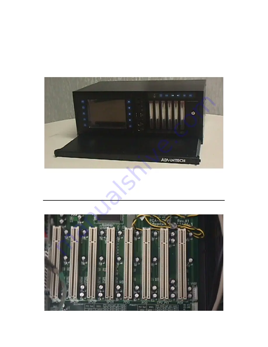
Please refer figure 2.8 to find a suitable cable connection for a backplane

Figure 2.8: Backplane

Summary of Contents for ATM-4023

Page 1: ...ATM 4023 4U Height 19 Rackmount Industrial Chassis with 6 4 LCD Display User Manual...

Page 2: ...is intended to be accurate and reli able However Advantech Co Ltd assumes no responsibility for its use nor for any infringements of the rights of third parties which may result from its use Acknowle...

Page 3: ...acement materials service time and freight Please consult your dealer for more details If you think you have a defective product follow these steps 1 Collect all the information about the problem enco...

Page 4: ...used in accordance with the instruction manual may cause harmful interference to radio communications Operation of this equipment in a residential area is likely to cause harmful interference in whic...

Page 5: ...carefully 2 Keep this User s Manual for later reference 3 Disconnect this equipment from any AC outlet before cleaning Use a damp cloth Do not use liquid or spray detergents for clean ing 4 For plug...

Page 6: ...l or you cannot get it to work according to the user s manual e The equipment has been dropped and damaged f The equipment has obvious signs of breakage 15 DO NOT LEAVE THIS EQUIPMENT IN AN ENVIRONMEN...

Page 7: ...htigkeit zu sch tzen 6 Bei der Aufstellung des Ger tes ist auf sicheren Stand zu achten Ein Kippen oder Fallen k nnte Verletzungen hervorrufen 7 Die Bel ftungs ffnungen dienen zur Luftzirkulation die...

Page 8: ...igt f Wenn das Ger t deutliche Anzeichen eines Defektes aufweist 15 VOSICHT Explisionsgefahr bei unsachgemaben Austausch der Batterie Ersatz nur durch densellben order einem vom Hersteller empfohlene...

Page 9: ...ure 2 5 HDD Drive Bay 11 Figure 2 6 HDD Holding Bracket 11 2 1 6 Optional Slim CD ROM Installation 12 Figure 2 7 Place for CD ROM Drawer 12 2 2 Backplane 12 Figure 2 8 Backplane 12 2 3 Cooling Fans 13...

Page 10: ...Manual x Figure A 1 PCA 6108P8 0A1 8 slot Pure PCI back plane 8 PCI Rev A101 22 Table A 1 Connector Descriptions 23 A 2 Connector Pin Definitions 24 A 3 PCI Routing Table 24 A 4 Mechanical Dimensions...

Page 11: ...CHAPTER 1 General Information This chapter introduces ATM 4023 and its usage Sections include Introduction General Specifications Passive Backplane Options CPU Card Options System Regulation Dimension...

Page 12: ...r various application requirements It is equipped with front accessible USB ports for easy USB device installation a PS 2 interface for an external keyboard and mouse an optional slim type CD ROM draw...

Page 13: ...ROM Drawer option 2 x 3 5 HDD I O Connectors 2 x Front accessible USB ports 1 x 6 pin PS 2 keyboard in front panel 1 x 6 pin PS 2 mouse in front panel 1 x Power On Off button in front panel 1 x Reset...

Page 14: ...ocket 370 Slot PC PCI 6870F 00A1 PIII Graded PCI Socket370 815E Slot PCA 6774F 02A1 PIII Graded ISA Socket 370 Slot PC PCA 6751 F0B2 P 266 ISA 586 Slot PC Part Number CPU Slot RAM MB VGA LAN USB CFC P...

Page 15: ...trial Automation platform with 6 4 LCD 4U Half Size Front Wiring PCA 6108P8 rev A1 PCI 6872F 00A1 PIII 250W ATM 4023H8 A2 8 PCI slot Industrial Automation platform with 6 4 LCD 4U Half Size Front Wiri...

Page 16: ...ATM 4023 User Manual 6 1 6 Dimensions 482 465 426 35 6 101 6 174 9 174 5 446 132 90 27 7 266 284 5...

Page 17: ...2 CHAPTER 2 System Setup This chapter shows how to setup your card and install accessories Sections include System Installation Backplane Cooling Fans Installing CPU Cards...

Page 18: ...er and Backplane Holder 1 First remove the chassis cover The top cover is fixed to the chassis by two thumbscrews 2 Release two thumbscrews on the rear upper location of the chassis 3 Lift the cover F...

Page 19: ...he LCD screen On the right there is a cover for the cable wiring There is also an optional slim type CD ROM drawer under the chassis The front panel interface is used for system reset power USB port T...

Page 20: ...to connect any USB interface device to the system KB MS IN Integrated PS 2 type 6 pin keyboard and mouse port OSD Controls LCD backlight On Off Menu Select Right Left Up Down 2 1 5 Drive Bay Installat...

Page 21: ...11 Chapter2 Figure 2 5 HDD Drive Bay Figure 2 6 HDD Holding Bracket...

Page 22: ...wer is integrated with the chassis with slide rails on both sides The user friendly CD ROM drawer can be released from the chassis by pressing the two latches on both sides of the drawer Refer the fig...

Page 23: ...s Figure 2 9 Cooling Fans 2 4 Installing CPU Cards To install single board computers and other add on boards 1 Remove the chassis cover 2 Take out the hold down clamp 3 Insert the SBC or add on cards...

Page 24: ...ATM 4023 User Manual 14 Figure 2 10 Connecting Cables for CPU Card Figure 2 11 Inserted CPU Card...

Page 25: ...2 CHAPTER 3 LCD Display Module and Accessories This chapter provides details on the LCD Module and its accessories Sections include LCD Module LCD Display Module Layout Indicator Board...

Page 26: ...lim and compact Display colors 262 144 colors Image conversions Up down and left right Active area outline area 62 3 Viewing direction 6 O clock Backlight lamps are replaceable 3 1 1 Mechanical Specif...

Page 27: ...17 Chapter3 Figure 3 1 Mechanical Drawing of TFT LCD Module part 1...

Page 28: ...ATM 4023 User Manual 18 Figure 3 2 Mechanical Drawing of TFT LCD Module part 2...

Page 29: ...19 Chapter3 3 2 LCD Display Module Layout Figure 3 3 LCD Module Rear 3 3 Indicator Board Figure 3 4 Indicator Board...

Page 30: ...ATM 4023 User Manual 20...

Page 31: ...2 APPENDIX A Backplane Layout...

Page 32: ...ATM 4023 User Manual 22 Appendix A Backplane Layout A 1 Connectors Figure A 1 PCA 6108P8 0A1 8 slot Pure PCI backplane 8 PCI Rev A101...

Page 33: ...econdary PCI Group VKB1 KB In from CPU card K B connector VKB2 KB Out 5 pin extemal K B connector HKB3 KB Out 5 pin extemal K B connector VBIG1 Big 4 Pin Power connector VAT1 AT Power VATX1 ATX Power...

Page 34: ...I Slot IDSEL PCI interrupt pin route INTA INTB INTC INTD PCI1 AD31 INTB INTC INTD INTA PCI2 AD30 INTC INTD INTA INTB PCI3 AD29 INTD INTA INTB INTC SPCI1 S_AD20 INTA INTB INTC INTD SPCI2 S_AD21 INTB IN...

Page 35: ...25 AppendixA A 4 Mechanical Dimensions A 5 Note There is support for 3 3 V PCI cards when an ATX power supply is used No 3 3 V PCI cards are supported if an AT power supply is used...

Page 36: ...ATM 4023 User Manual 26...

Reviews: