17
Chapter 4
4.2 Camera Select
The unit provides sixteen camera inputs. Every four channels are grouped
for easy and prompt display operation. For example, Ch 1, Ch 2, Ch 3 and
Ch 4 are set for Group 1; Ch 5, Ch 6, Ch 7 and Ch 8 are for Group 2 and
so on.
The unit provides 4 camera groups. You can use group select buttons on
the front panel to select specified group for real-time display.
You can use the
button or group select buttons for different groups of
channel display.
Example:
1. When you choose (----), all cameras are off.
2. When you choose (1234), all cameras are displayed.
3. When you choose (---4), only the fourth group is displayed.
Video Loss
Note:
The VIDEO LOSS signal will be displayed and
the built-in alarm buzzer will be sound for video
connection signal loss or connection failure.
Note:
In each mode
mode, you can use the
button to display the full-screen format of each
channel by rotation.
回
田
Summary of Contents for DVR-520
Page 1: ...DVR 520 4 Channel Smart DVR Series with Removable HDD Bay User s Manual...
Page 12: ...DVR 520 User s Manual xii...
Page 24: ...DVR 520 User s Manual 10...
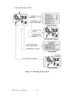
Page 28: ...DVR 520 User s Manual 14 OnScreen Display OSD Figure 3 3 Powering on the system...
Page 46: ...DVR 520 User s Manual 32...
Page 62: ...DVR 520 User s Manual 48...
Page 66: ...DVR 520 User s Manual 52...

