background image

27

Chapter 4  

In normally open mode, if the cable between the sensor and the unit is cut 
by an intruder, the unit starts recording. In normally closed mode, if the 
cable between the sensor and the unit is cut by an intruder, the unit stops 
recording.

4.13  How to Operate Motion Detection Recording

Follow the steps given below to activate motion-detection recording.
1.

Please go to “SENSOR SETUP” menu as shown in the figure.

2.

Select the required motion option.

3.

After the selection, please go back to the MAIN MENU and go to 
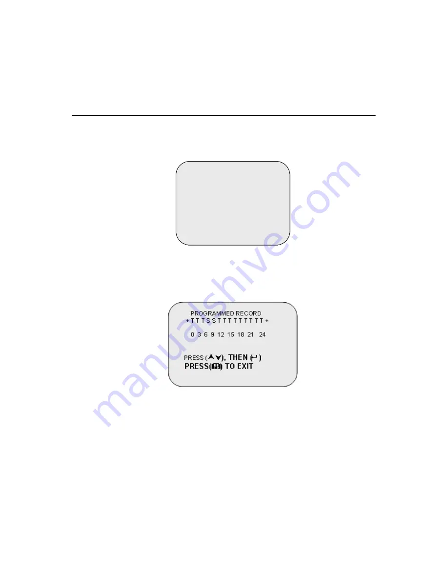
“PROGRAMMED RECORD” to activate the alarm setting. 


Note:

Setting “PROGRAMMED RECORD” is neces-
sary for starting the operation of motion detection 
recording.

SENSOR SETUP

SENSOR RECORD TIME           15
ALARM OUT TIME                      20
CHANNEL-1   TYPE: N-C  
CHANNEL-2   TYPE: N-O
CHANNEL-3   TYPE:NORMAL 
CLOSE
CHANNEL-4   TYPE:NOT 
INSTALLED

PRESS (

¿À

), THEN (

)

PRESS(


) TO EXIT

Summary of Contents for DVR-520

Page 1: ...DVR 520 4 Channel Smart DVR Series with Removable HDD Bay User s Manual...

Page 2: ...form or by any means without the prior written permission of Advantech Co Ltd Information provided in this manual is intended to be accurate and reli able However Advantech Co Ltd assumes no responsib...

Page 3: ...acement materials service time and freight Please consult your dealer for more details If you think you have a defective product follow these steps 1 Collect all the information about the problem enco...

Page 4: ...harge and EMI leakage we strongly recom mend the use of CE compliant industrial enclosure products FCC Class A This equipment has been tested and found to comply with the limits for a Class A digital...

Page 5: ...eral attachments Description of your software operating system version applic tion software etc A complete description of the problem The exact wording of any error messages Document Feedback To assis...

Page 6: ...n the power cord so that people cannot step on it Do not place anything over the power cord 10 All cautions and warnings on the equipment should be noted 11 If the equipment is not used for a long tim...

Page 7: ...ie diese Anleitung f r den sp teren Gebrauch auf 3 Vor jedem Reinigen ist das Ger t vom Stromnetz zu trennen Ver wenden Sie Keine Fl ssig oder Aerosolreiniger Am besten dient ein angefeuchtetes Tuch z...

Page 8: ...gsanleitung entsprechend funktioniert oder Sie mit Hilfe dieser Anleitung keine Verbesse rung erzielen e Das Ger t ist gefallen und oder das Geh use ist besch digt f Wenn das Ger t deutliche Anzeichen...

Page 9: ...y Guidelines Checking the Power Cords Use the exact type of power cords as required Be sure to use power cord s that came with safety certifications The power cord s must be compliant with the AC volt...

Page 10: ...rical shock Use rubber mats specifically designed as electrical insulators when working with computer systems The power supply or power cord must include a grounding plug and must be plugged into grou...

Page 11: ...rical circuits or being pulled into a cooling fan After removing the components or chassis covers from the system place them on a table for safeguard Be sure to remove any jewelry or metal objects bef...

Page 12: ...DVR 520 User s Manual xii...

Page 13: ...y 12 Figure 3 1 HDD Checking in progress 12 Figure 3 2 Real Time Display Mode 12 Figure 3 3 Powering on the system 14 Chapter 4 Operation Guide 16 4 1 Main Menu 16 4 2 Camera Select 17 4 3 Record Sele...

Page 14: ...Table B 1 Playback buttons 45 B 2 Searching Files 46 B 3 Backing up files as AVI 47 Appendix C Video Quality Settings Table 50 C 1 NTSC Format 50 Table C 1 Recording time vs video quality NTSC 50 Figu...

Page 15: ...2 CHAPTER 1 DVR 520 Introduction This section introduces the Digital Video Recorder DVR This section includes Front Panel Remote IR Controller Rear Panel...

Page 16: ...from up to 4 channels at the same time It adopts a digital image compression technology to compress the input channel video streams and uses a HDD to record the compressed video stream This user manu...

Page 17: ...s to play the recorded video stream faster 4 Playback button Pause button press to start playback and press to pause the video playback 5 Reverse press to play backwards 6 Select button press to chang...

Page 18: ...deo output 3 Monitor Second Video output 4 Video input 5 Video loop through 6 Sensor input alarm output 4 sensor inputs and one alarm output 7 NTSC PAL switch 8 DC in 12 Volts 9 Audio in out 10 LAN RJ...

Page 19: ...2 DVR Installation This section explains the installation of the DVR 520 Digital Video Recorder DVR This section includes Video Output Connection Video Input Connection Sensor Installation Alarm Inst...

Page 20: ...Output Connection TV or LCD Monitor Please connect a TV or LCD monitor to the unit over the video output connector The unit provides one S Video input two BNC connectors and one VGA output Figure 2 1...

Page 21: ...procedures are as follows 1 Connect the video signal line Connect the video signal line to the unit 2 Connect the camera power line Connect the camera s adaptor to the camera and plug in the adaptor...

Page 22: ...is as follows The maximum power requirement of the sensor device is up to 1 5 V 50 mA 1 Connect the sensor signal line Connect the video signal line to the unit The Sensor signal terminal is at the u...

Page 23: ...he normal state but when the alarm is activated the switch is closed to power the alarm The circuitry is shown below There are two simple steps for the installation of the alarm 1 Prepare the power su...

Page 24: ...DVR 520 User s Manual 10...

Page 25: ...2 CHAPTER 3 Powering Up the Unit This section shows the power up screens of the Digital Video Recorder DVR This section includes On screen display...

Page 26: ...d play Apply power and switch on After the unit is powered on the unit checks the HDD for several sec onds then displays the following screen Figure 3 1 HDD Checking in progress Figure 3 2 Real Time D...

Page 27: ...13 Chapter3 Notes 1 Make sure the HDD is off before removing the drive 2 Once you resume the initial setting the right information will be displayed on the screen Turn off the unit and restart...

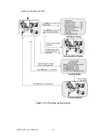
Page 28: ...DVR 520 User s Manual 14 OnScreen Display OSD Figure 3 3 Powering on the system...

Page 29: ...20 Digital Video Recorder DVR This section includes Main Menu Group Select Record Select Record Frame Rate Video Quality Record Schedule Sub Menu Time Set Backup Through USB Port Group Display Time Ha...

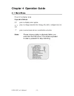
Page 30: ...on Buttons press to display menu option press to change menu field or change the unit s configuration val ues press to select menu item or confirm the selection Note Please stop recording or playback...

Page 31: ...t specified group for real time display You can use the button or group select buttons for different groups of channel display Example 1 When you choose all cameras are off 2 When you choose 1234 all...

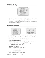
Page 32: ...me events dur ing the recording period 4 4 Record Mode There are two kinds of recording modes each mode full screen mode and quad screen mode when you select mode you can view the full screen display...

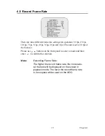
Page 33: ...1 fps The unit is set to 30 fps at the factory Please use buttons on the front panel to select a mode and then enter to confirm the selection Note Recording Frame Rate The higher the record frame rat...

Page 34: ...Record Schedule Enter into this option to change a recording schedule during a day 24 hour period Numbers above indicate the time duration of 24 hours T Letter indicates recording S Letter indicates s...

Page 35: ...55555 When the new password is accepted the board will flash the following screen message PASSWORD changed The message will blink 5 times Then the display goes back to the SUB MENU Note Sensor Recordi...

Page 36: ...tically return to SUB MENU Time Set Enter this option to change the date and time The unit provides yyyy mm dd or dd mm yyyy variants which reflect regional preferences Table 4 1 Front panel button de...

Page 37: ...ubmenu of the unit The link ing will take around 30 seconds The connection is then ready for PC backup as Linked is indicated on the screen 3 Open the PC viewer on the PC after the PC identifies the u...

Page 38: ...rom 1 sec to 9 sec between displays for the 4 channels Warning Please don t press the MENU button during linking it could lead to an unpredictable error on your PC Note Please refer to Appendix C for...

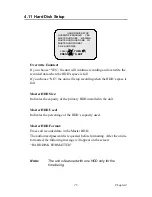
Page 39: ...led in the unit Master HDD Used Indicates the percentage of the HDD s capacity used Master HDD Format Erases all recorded data in the Master HDD The authorized password is requested before formatting...

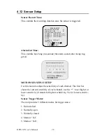
Page 40: ...hows the current sensitivity of each channel use the to set higher or lower sensitivity 0 stands for highest sensitivity 9 is for lowest sensitiv ity Sensor Trigger Modes The unit provides 5 different...

Page 41: ...ivate motion detection recording 1 Please go to SENSOR SETUP menu as shown in the figure 2 Select the required motion option 3 After the selection please go back to the MAIN MENU and go to PROGRAMMED...

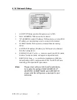
Page 42: ...P address IP address A Will need to be obtained from the routing device 6 DVR ID ON LAN Use the button to specify the DVR s identi fication Twenty six letters will appear in sequential order 7 DHCP ON...

Page 43: ...ing CPU 1 GHZ or above System memory 256 MB or above VGA memory 32 MB OS Windows 2000 XP 2 Please assign 14337 14338 to the Port to install the DVR in a LAN with a static IP address under a router wit...

Page 44: ...ess this button to fast forward the recorded stream The unit provides four levels of fast forward playback speeds Press the button to change the playing speed Press once for two times faster x 2 than...

Page 45: ...tton to play the recorded stream back wards pause button Press this button to pause the playback or to advance a single frame at a time Note The reverse playback speed depends on the fps the number of...

Page 46: ...DVR 520 User s Manual 32...

Page 47: ...orking This section explains the networking details of the Digital Video Recorder DVR This section includes Connecting PC to the DVR DVR Control Capture and Playback on PC DVR Management AVI File Sing...

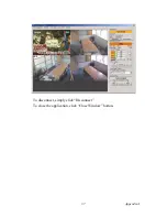
Page 48: ...ideo over the internet from a remote location You can also capture and convert video from the unit into an AVI file or JPEG file and play the stored video later on Please follow the instructions below...

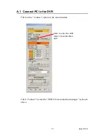
Page 49: ...ppendixA A 1 Connect PC to the DVR Click on the Connect option in the main window Click Connect to enter the DVR Client connection manager as shown above Click to enter the DVR Client Connection Man a...

Page 50: ...lt value is 111111 Nickname If you have configured the DHCP settings in the DVR you can connect to the DVR by clicking on Search DVR There will be a list of DVRs in the Nickname list box Select the on...

Page 51: ...37 AppendixA To disconnect simply click Disconnect To close the application click Close Window button...

Page 52: ...0 User s Manual 38 A 2 DVR Control The panel shown in the following figure operates exactly as the DVR operation buttons to allow you to remotely control the DVR for live view record and playback func...

Page 53: ...r PC s hard disk The DVR client creates a stream_files folder where the file is located When the client is record ing the Capture Play status indicator shows REC as the current sta tus A 3 2 Playback...

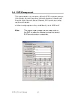
Page 54: ...Record Frame Rate Alarm On Duration Alarm Record Duration Input Channels Record Channels DVR system time setting and Record Schedule All these settings operate as they would directly on the DVR itsel...

Page 55: ...d video data into an AVI file You will see the following dialog box for saving the AVI file After specifying the file name and confirming click on Backup to AVI to start the conversion Click on this b...

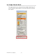
Page 56: ...R 520 User s Manual 42 A 6 Single Channel Scaler The single channel scaler is functional only in single channel mode If you are viewing a single channel you can scale up down by selecting these option...

Page 57: ...2 APPENDIX B PC Viewer This section explains the PC Viewer of the Digital Video Recorder DVR This section includes Installing PC Viewer Searching files Backing files up as AVI...

Page 58: ...DVR 520 User s Manual 44 Appendix B PC Viewer B 1 Installing PC Viewer Please follow the steps given below to complete the installation of PC Viewer Play Search Capture Backup to AVI...

Page 59: ...to start the playback after data search Backup to AVI button a Click to convert the data into an AVI file and save it the PC Capture Button a Click to a snapshot of the data as a BMP file HDD selectio...

Page 60: ...or selecting an event You will see the dialog box as shown below Click on the Play button to start playback after confirming the retrieval This is a required step to initially activate the playback E...

Page 61: ...n the Backup to AVI button to convert the desired video data into an AVI file You will see the following dialog box for saving the AVI file Specify the file name and confirm it The conversion will sta...

Page 62: ...DVR 520 User s Manual 48...

Page 63: ...2 APPENDIX C Video Quality Settings Tables This section lists the Video Quality Settings of the Digital Video Recorder DVR This section includes NTSC Format PAL Format...

Page 64: ...C 1 Recording time vs video quality NTSC Frames Second 1 2 3 4 5 7 10 15 30 MODE HI 897H 448H 299H 223H 179H 104H 89H 59H 29H NORMAL 1092H 546H 364H 273H 218H 152H 109H 72H 36H LO 1365H 682H 455H 340H...

Page 65: ...Second 1 2 3 4 6 8 12 25 MODE HI 448H 299H 223H 179H 104H 89H 59H 29H NORMAL 546H 364H 273H 218H 152H 109H 72H 36H LO 682H 455H 340H 273H 191H 136H 91H 45H MODE HI 345H 230H 172H 138H 96H 69H 46H 23H...

Page 66: ...DVR 520 User s Manual 52...

Reviews: