9
DVS-500 User Manual
Chapter 2
S
ystem
Setup
2.1.2
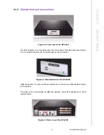
Chassis front and rear sections
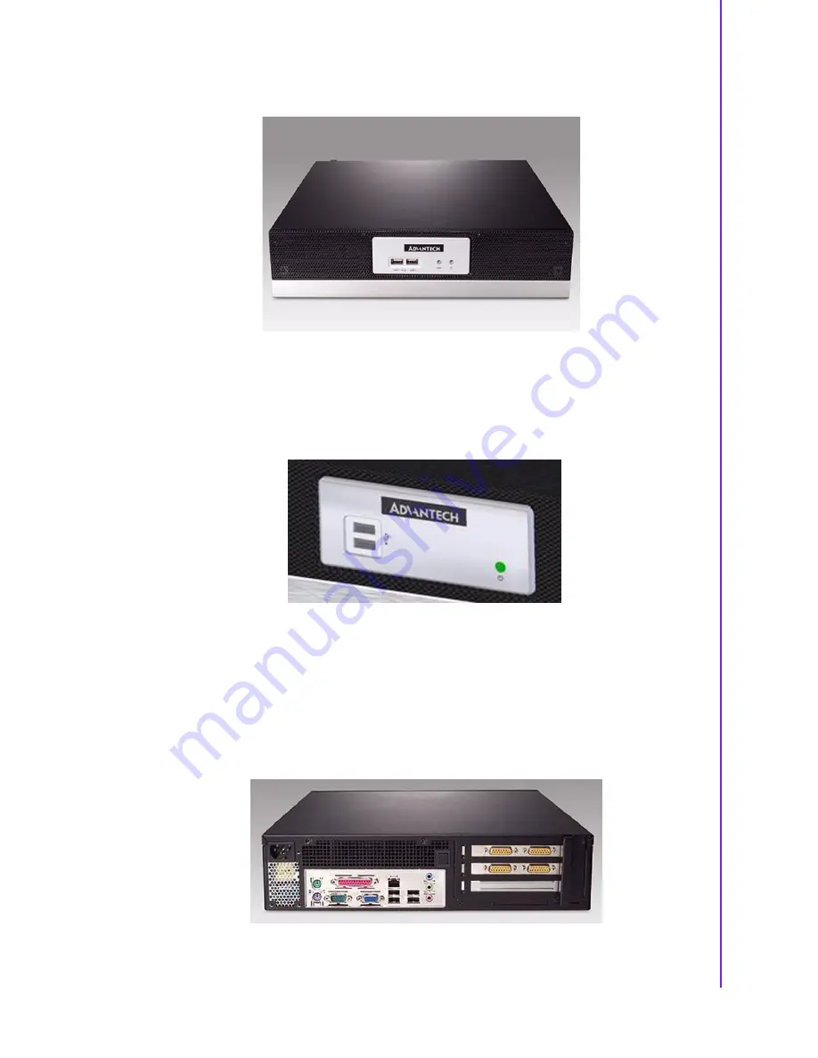
Figure 2.3 Front view of the DVS-500
The LED indicator is on the right side of the front cover, indicating the power status.
The 2 x USB connectors are on the left side of the front panel.
Figure 2.4 Standard bezel of the DVS-500
USB connectors: You can use these connectors to connect any USB interface device
to the system.
The back of the unit includes an M/B rear window, 2-slot I/O brackets and 1-D-I/O
module option.
Figure 2.5 Rear view of the DVS-500
Summary of Contents for DVS-500
Page 1: ...User Manual DVS 500 Industrial Compact Platform for PC Based Video Surveillance...
Page 8: ...DVS 500 User Manual viii...
Page 9: ...Chapter 1 1 General Information...
Page 13: ...5 DVS 500 User Manual Chapter 1 General Information...
Page 14: ...DVS 500 User Manual 6...
Page 15: ...Chapter 2 2 System Setup...
Page 26: ...DVS 500 User Manual 18...
Page 27: ...Appendix A A Exploded Diagram...
Page 29: ...21 DVS 500 User Manual Appendix A Exploded Diagram...


