background image

DVS-500 User Manual

iv

Packing List

Before setting up the system, check that the items listed below are included and in
good condition. If items received do not match those in the table, please contact your
dealer immediately.

„

Item 

„

Box 

Safety Instructions

1.

Read these safety instructions carefully.

2.

Keep this User Manual for later reference.

3.

Disconnect this equipment from any AC outlet before cleaning. Use a damp 
cloth. Do not use liquid or spray detergents for cleaning.

4.

For plug-in equipment, the power outlet socket must be located near the equip-
ment and must be easily accessible.

5.

Keep this equipment away from humidity.

6.

Put this equipment on a reliable surface during installation. Dropping it or letting 
it fall may cause damage.

7.

The openings on the enclosure are for air convection. Protect the equipment 
from overheating. DO NOT COVER THE OPENINGS.

8.

Make sure the voltage of the power source is correct before connecting the 
equipment to the power outlet.

9.

Position the power cord so that people cannot step on it. Do not place anything 
over the power cord.

10.

All cautions and warnings on the equipment should be noted.

11.

If the equipment is not used for a long time, disconnect it from the power source 
to avoid damage by transient overvoltage.

12.

Never pour any liquid into an opening. This may cause fire or electrical shock.

13.

Never open the equipment. For safety reasons, the equipment should be 
opened only by qualified service personnel.

14.

If one of the following situations arises, have the equipment checked by service 
personnel:

The power cord or plug is damaged.

Liquid has spilled into the equipment.

The equipment has been exposed to moisture.

The equipment does not work well, or you cannot get it to work according to 

the user's manual.

The equipment has been dropped and damaged.

The equipment has obvious signs of breakage.

15.

DO NOT LEAVE THIS EQUIPMENT IN AN ENVIRONMENT WHERE THE 
STORAGE TEMPERATURE MAY GO BELOW -20° C (-4° F) OR ABOVE 60° C 
(140° F). THIS COULD DAMAGE THE EQUIPMENT. THE EQUIPMENT 
SHOULD BE IN A CONTROLLED ENVIRONMENT.

16.

CAUTION: DANGER OF EXPLOSION IF BATTERY IS INCORRECTLY 
REPLACED. REPLACE ONLY WITH THE SAME OR EQUIVALENT TYPE 
RECOMMENDED BY THE MANUFACTURER, DISCARD USED BATTERIES 
ACCORDING TO THE MANUFACTURER'S INSTRUCTIONS.

The sound pressure level at the operator's position according to IEC 704-1:1982 is
no more than 70 dB (A).

Summary of Contents for DVS-500

Page 1: ...User Manual DVS 500 Industrial Compact Platform for PC Based Video Surveillance...

Page 2: ...ation provided in this manual is intended to be accurate and reliable How ever Advantech Co Ltd assumes no responsibility for its use nor for any infringe ments of the rights of third parties which ma...

Page 3: ...curs 2 Call your dealer and describe the problem Please have your manual product and any helpful information readily available 3 If your product is diagnosed as defective obtain an RMA return merchand...

Page 4: ...ns and warnings on the equipment should be noted 11 If the equipment is not used for a long time disconnect it from the power source to avoid damage by transient overvoltage 12 Never pour any liquid i...

Page 5: ...fen niemals Gegenst nde oder Fl ssigkeiten in das Ger t gelangen Dies k nnte einen Brand bzw elektrischen Schlag aus l sen 13 ffnen Sie niemals das Ger t Das Ger t darf aus Gr nden der elektrischen Si...

Page 6: ...age To avoid electrical shock always disconnect the power from your PC chassis before you work on it Don t touch any components on the CPU card or other cards while the PC is on Disconnect power befor...

Page 7: ...emove two screws from drive bay 11 Figure 2 10Remove drive bay from main chassis 11 Figure 2 11Remove 4 8 screws from drive bay with one two HDD s 12 Figure 2 12Lift HDD s from drive bay 12 Figure 2 1...

Page 8: ...DVS 500 User Manual viii...

Page 9: ...Chapter 1 1 General Information...

Page 10: ...eal platform for applications like retail community fac tory or Small and Medium Enterprises 1 2 Specifications General Construction Heavy duty steel chassis Indicators on front panel LEDs for Power D...

Page 11: ...3 DVS 500 User Manual Chapter 1 General Information 1 4 Dimensions Figure 1 1 Dimension Diagram 370 380 370 88 Unit mm...

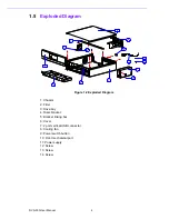
Page 12: ...ed Diagram 1 Chassis 2 Filter 3 Drive bay 4 Riser bracket 5 Bracket linking bar 6 Cover 7 2 port vertical USB connector 8 Cooling fan 9 Power switch button 10 Front mechanical part 11 Power supply 12...

Page 13: ...5 DVS 500 User Manual Chapter 1 General Information...

Page 14: ...DVS 500 User Manual 6...

Page 15: ...Chapter 2 2 System Setup...

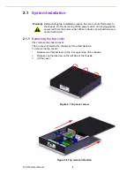
Page 16: ...s on the rear upper side of the chassis 2 Release one thumbscrew on the left side of the chassis 3 Lift the cover Figure 2 1 Top cover screw Figure 2 2 Top removal direction Warning Before starting th...

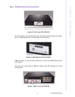
Page 17: ...ront cover indicating the power status The 2 x USB connectors are on the left side of the front panel Figure 2 4 Standard bezel of the DVS 500 USB connectors You can use these connectors to connect an...

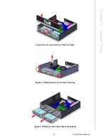
Page 18: ...t bezel to the frame 3 Lift the front bezel from the main chassis 4 Remove the two screws securing the drive bay 5 Remove the drive bay from the chassis 6 Insert the drives into their proper locations...

Page 19: ...11 DVS 500 User Manual Chapter 2 System Setup Figure 2 8 Lift up and remove from the frame Figure 2 9 Remove two screws from drive bay Figure 2 10 Remove drive bay from main chassis...

Page 20: ...DVS 500 User Manual 12 Figure 2 11 Remove 4 8 screws from drive bay with one two HDD s Figure 2 12 Lift HDD s from drive bay Figure 2 13 Securing HDD to the drive bay...

Page 21: ...el The momentary switch is suitable for use with an ATX power supply such as a 180W or 220W Flex type Please plug the 20 pin ATX power connector to your ATX M B and then connect the POWER SW wire to y...

Page 22: ...0 The LED bezel only has one LED indicator which indicates power status The LED is green when the power supply is working normally Figure 2 18 The customized bezel of the DVS 500 These two types of be...

Page 23: ...operly attached to the motherboard If the problem persists consult an experienced technician 2 3 3 Power supply The DVS 500 power supply supports both a full range of connectors and an inner cooler sy...

Page 24: ...DVS 500 User Manual 16 Figure 2 20 DVS 500 power supply Figure 2 21 Rear view release screws from power supply Figure 2 22 Lift the power supply...

Page 25: ...system has stopped A defective fan should be replaced immediately please refer to Figure 2 23 The con nector is a standard motherboard fan plug Additionally if the filter is blocked with dust or othe...

Page 26: ...DVS 500 User Manual 18...

Page 27: ...Appendix A A Exploded Diagram...

Page 28: ...ded Diagram 1 Chassis 2 Filter 3 Drive bay 4 Riser bracket 5 Bracket linking bar 6 Cover 7 2 port vertical USB connector 8 Cooling fan 9 Power switch button 10 Front mechanical part 11 Power supply 12...

Page 29: ...21 DVS 500 User Manual Appendix A Exploded Diagram...

Page 30: ...tions are subject to change without notice No part of this publication may be reproduced in any form or by any means electronic photocopying recording or otherwise without prior written permis sion of...

Reviews: