


3
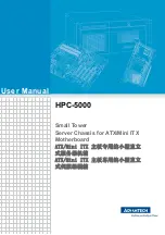
HPC-5000 User Manual /
用户手册
Chapter 1
G
eneral
Information
概述 產品資訊
构造:重型钢
磁盘容量:2 个 3.5" 或是 1 个 3.5" + 1 个 2.5" 内置硬盘托架
LED 指示灯:电源开关自带 LED
前面板上的开关和按钮:电源开关
前部 I/O 接口:2 个 USB2.0 以及 2 个 USB3.0 接口
冷却系统:1 个 12 cm x 12 cm (82 CFM) 后置 PWM 风扇; 1 个选配 8cm 下方风扇
重量:10 公斤 ( 机箱 + 电源 )
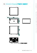
产品尺寸(W x H x D):192 x 376.7 x 338.5 (7.56" x 14.83" x 13.33), 含
机箱脚垫与防盗锁片
構造:重型鋼
磁碟容量:2 個 3.5" 或是 1 個 3.5" + 1 個 2.5" 內置硬碟托架
LED 指示燈:電源開關自帶 LED
前面板上的開關和按鈕:電源開關
前部 I/O 接頭:2 個 USB2.0 以及 2 個 USB3.0 介面
冷卻系統:1 個 12 cm x 12 cm (82 CFM) 後置 PWM 風扇; 1 個選配 8cm 下方風扇
重量:10 公斤 ( 機箱 + 電源 )
產品尺寸(W x H x D):192 x 376.7 x 338.5 (7.56" x 14.83" x 13.33), 含
機箱腳墊與防盜鎖片
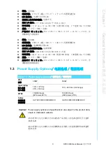
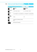
1.3
Power Supply Options
/ 电源选项 / 電源選項
Table 1.1: Power supply options
/ 电源选项 / 電源選項
Watt
功率
300W
500W
Input rating
输入电压
輸入電壓
100 ~ 127 Vac
200 ~ 240 Vac
100 ~ 240 Vac (Full range)
MTBF
100,000 hours
(80% load; 25°C)
100,000 hours
(100% load; 25°C)
Safety
安规认证
安規認證
UL/TUV/CB/CCC/BSMI/KCC
UL/TUV/CB/CCC/BSMI/KCC
Caution!
Power supply options and specifications are subject to the product data-
sheet on Advantech website.
请以研华公司官方网站公告的该机箱产品型录上的电源选项料号与电源
规格为准。
請以研華公司官方網站公告的該機箱產品型錄上的電源選項料號與電源
規格為準。
Summary of Contents for HPC-5000
Page 10: ...HPC 5000 User Manual x...
Page 13: ...Chapter 1 1 General Information...
Page 18: ...HPC 5000 User Manual 6...
Page 19: ...Chapter 2 2 System Setup...
Page 23: ...Chapter 3 3 Operation...
Page 26: ...HPC 5000 User Manual 14...
Page 27: ...Appendix A A Exploded Diagram Parts List...
Page 30: ...HPC 5000 User Manual 18...