background image

HPC-5000 User Manual / 

用户手册

12

3.1

The Front and Rear Panel 

/ 前后面板 / 前後面板

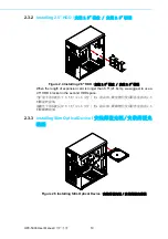
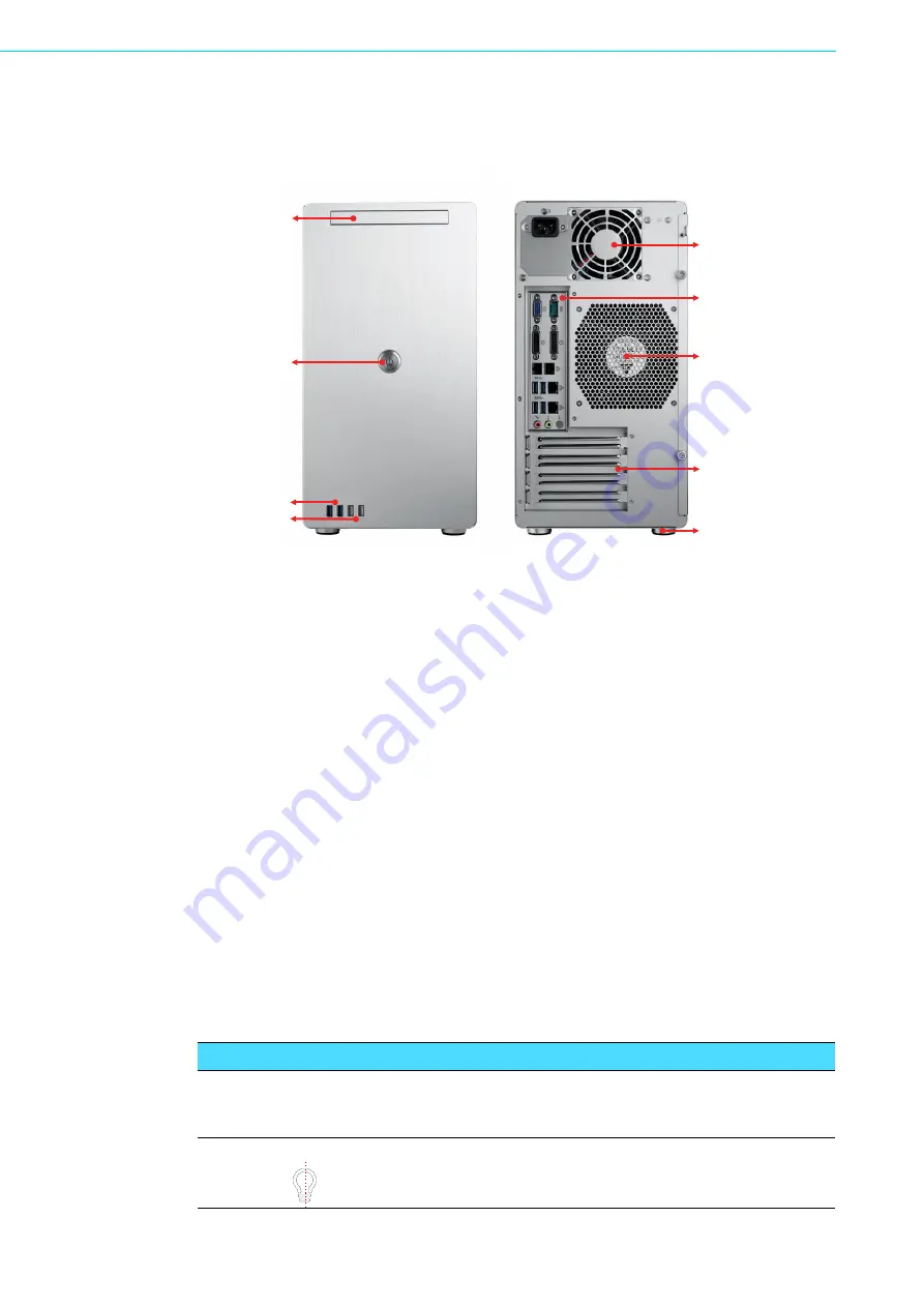
Figure 3.1 The Front and Rear Panel 

/ 前后面板 / 前後面板

3.2

Switch, Buttons and I/O Interfaces

/ 开关和按钮 /

開關和按鈕

Momentary Power switch:

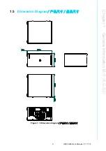
 Press this switch to turn the system power on or off.

Please use system shutdown or press this switch for few seconds to turn off the sys-
tem ATX power.

电源开关:按下此按钮可开启或关闭系统电源。请使用系统关机或持续按下此按钮数
秒钟以关闭系统 ATX 电源。

電源開關:按下此按鈕可開啟或關閉系統電源。請使用系統關機或持續按下此按鈕數
秒鐘以關閉系統 ATX 電源。

USB 2.0/3.0 ports:

 For connecting a wide range of USB devices for data transfer,

backup or input.

USB 2.0/3.0 接口:此接口可连接各种 USB 设备用于数据传输、备份或输入。
USB 2.0/3.0 接頭:此接頭可連接各種 USB 設備用於資料傳輸、備份或輸入。

3.2.1

LED indicators for System Status

/ 系统指示灯 / 系統指示燈


2x USB 3.0

Power button  /

电源按钮 /
電源按鈕

Slim ODD Tray  /

薄型ODD托架

2x USB 2.0

300/500W Single  PSU /

300/500W单PSU /
300/500W單PSU

Rear IO space  /

后部IO / 後部

12cm system fan  /

12cm系统风扇 /
12cm系統風扇

4 expansion card slot  /

4个扩展插槽 /
4個擴展插槽

Chassis feet  /

机箱脚垫 / 機箱腳墊

Front side view 

前面板

Rear side view /

后面板 / 後面板

Table 3.1: LED Indicator functions

/ 系统指示灯 / 系統指示燈

LED

Description

说明
說明

Blue

蓝色
藍色

Power

/ 电源 / 電源

System Power

系统电源
系統電源

Normal

正常

Summary of Contents for HPC-5000

Page 1: ...User Manual HPC 5000 Small Tower Server Chassis for ATX Mini ITX Motherboard ATX Mini ITX ATX Mini ITX...

Page 2: ...d in any form or by any means without the prior written permission of Advantech Co Ltd Information provided in this manual is intended to be accurate and reliable How ever Advantech Co Ltd assumes no...

Page 3: ...F it may damage the equipment 9 The openings on the enclosure are for air convection Protect the equipment from overheating DO NOT COVER THE OPENINGS 10 Make sure the voltage of the power source is co...

Page 4: ...e and 2 this device must accept any interference received including interference that may cause undesired operation 20 CAUTION Always completely disconnect the power cord from your chassis whenever yo...

Page 5: ...v HPC 5000 User Manual 15 16 17 18 CD IEC 60825 19 FCC 15 1 2 20 21 22 1 2 3 4 5 6 7 8 0 C 32 F 40 C 104 F 9 10 11 12 13 14 15 16 CLASS I LASER PRODUCT KLASS I LASER PRODUKT...

Page 6: ...trial environments Whether your new Advantech equipment is destined for the labo ratory or the factory floor you can be assured that your product will provide the reliability and ease of operation fo...

Page 7: ...pplication requirements or spe cific information on the installation and operation of any of our products Product Warranty Advantech warrants to you the original purchaser that each of its products wi...

Page 8: ...as defective obtain an RMA return merchandise authorization number from your dealer This allows us to process your return more quickly 4 Carefully pack the defective product a fully completed Repair a...

Page 9: ...ely We have carefully inspected the product mechanically and electrically before shipment It should be free of marks and scratches and in perfect working order upon receipt As you unpack the product c...

Page 10: ...HPC 5000 User Manual x...

Page 11: ...rboard 9 2 3 Installing Disk Drives 9 2 3 1 Installing 3 5 HDD 3 5 3 5 9 Figure 2 3 Installing 3 5 HDD 3 5 3 5 9 2 3 2 Installing 2 5 HDD 2 5 2 5 10 Figure 2 4 Installing 2 5 HDD 2 5 2 5 1 0 2 3 3 Ins...

Page 12: ...xploded Diagrams Parts List 16 Table A 1 Parts list 17 Appendix B Power board cable instruction 19 B 1 Top view of power distribution board 20 B 2 Connector pin assignment 21 Table B 1 CN1 21 Table B...

Page 13: ...Chapter 1 1 General Information...

Page 14: ...ending on the high or low temperatures inside the chassis A wide range of standard computing peripherals can be integrated with these chassis to accommodate robust applications in rugged environments...

Page 15: ...12 cm x 12 cm 82 CFM PWM 1 8cm 10 W x H x D 192 x 376 7 x 338 5 7 56 x 14 83 x 13 33 1 3 Power Supply Options Table 1 1 Power supply options Watt 300W 500W Input rating 100 127 Vac 200 240 Vac 100 24...

Page 16: ...ronment specifications Environment Operating Non operating Temperature 0 40 C 32 104 F 40 70 C 40 158 F Humidity 10 95 40 C non condensing 10 95 60 C non condensing Vibration 5 500Hz 1G rms 2 G Shock...

Page 17: ...5 HPC 5000 User Manual Chapter 1 General Information 1 5 Dimension Diagram Figure 1 1 Dimension diagram...

Page 18: ...HPC 5000 User Manual 6...

Page 19: ...Chapter 2 2 System Setup...

Page 20: ...Removing the Side Cover Note Use caution when installing or operating the components with the chas sis open Be sure to turn off the power unplug the power cord and ground yourself by touching the meta...

Page 21: ...HPC 5000 User Manual Chapter 2 System Setup 2 2 Installing Motherboard Figure 2 2 Installing Motherboard 2 3 Installing Disk Drives 2 3 1 Installing 3 5 HDD 3 5 3 5 Figure 2 3 Installing 3 5 HDD 3 5 3...

Page 22: ...ure 2 4 Installing 2 5 HDD 2 5 2 5 When the length of expansion card is longer than 8 5 21 6cm we suggest to use a 2 5 HDD bracket in the second HDD space 8 5 21 6 2 5 8 5 21 6 2 5 2 3 3 Installing Sl...

Page 23: ...Chapter 3 3 Operation...

Page 24: ...sys tem ATX power ATX ATX USB 2 0 3 0 ports For connecting a wide range of USB devices for data transfer backup or input USB 2 0 3 0 USB USB 2 0 3 0 USB 3 2 1 LED indicators for System Status 2x USB...

Page 25: ...o ATX Mini ITX motherboard Micro ATX Mini ITX 12cm system fan 300 500W Single PSU 300 500W PSU 300 500W PSU Keylock bracket Keylock 8cm system fan optional 8cm 8cm 2 5 3 5 HDD space 2 5 3 5 HDD 2 5 3...

Page 26: ...HPC 5000 User Manual 14...

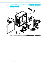
Page 27: ...Appendix A A Exploded Diagram Parts List...

Page 28: ...HPC 5000 User Manual 16 A 1 Exploded Diagram Parts List Figure A 1 Exploded Diagrams Parts List...

Page 29: ...chassis 9 Air filter bracket 2 Power supply unit 10 HDD bracket 3 Side cover 11 Slim ODD bracket 4 Chassis feet 12 Front USB port cable USB USB 5 Air filter cover 13 Front USB port cable bracket USB U...

Page 30: ...HPC 5000 User Manual 18...

Page 31: ...Appendix B B Power board cable instruction...

Page 32: ...or 8pin 12V connector of PCIe slot PCIe 4 8 12V PCIe 4 8 12V 1700025828 01 1 Default in accessory box CN2 8P connector to 6 2 connector for GPU card power 8P 6 2 GPU 8P 6 2 GPU 1700025829 01 1 Option...

Page 33: ...GND 2 Black GND 3 Black GND 4 Black GND 5 Yellow 12VDC 6 Yellow 12VDC 7 Yellow 12VDC 8 Yellow 12VDC Table B 2 CN2 3 4 5 6 7 Pin number Color Signal 1 Yellow 12VDC 2 Yellow 12VDC 3 Yellow 12VDC 4 Black...

Page 34: ...No part of this publication may be reproduced in any form or by any means electronic photocopying recording or otherwise without prior written permis sion of the publisher All brand and product names...

Reviews: