background image

v

HPC-5000 User Manual / 

用户手册


15.

请不要自行打开设备。为了确保您的安全,请由经过认证的工程师来打开设备。

16.

如遇下列情况,请由专业人员来维修:



电源线或者插头损坏;



设备内部有液体流入;



设备曾暴露在过于潮湿的环境中使用;



设备无法正常工作,或您无法通过用户手册来使其正常工作;



设备跌落或者损坏;



设备有明显的外观破损。

17.

注意:计算机配置了由电池供电的实时时钟电路,如果更换错误的电池,将有爆
炸的危险。因此,只可以使用制造商推荐的同一种或者同等型号的电池进行替
换。请按照制造商的指示处理旧电池。

18.

计算机提供的 CD 光盘驱动,已符合各种安全标准,包括 IEC 60825。

19.

本设备符合 FCC 规则第 15 款的规定。操作受如下两个条件限制:
(1) 本设备不得产生有害的干扰,而且 
(2) 本设备必须能经受干扰,包括可能引起意外操作的干扰。

20.

注意:无论何时进行操作,请务必完全断开机箱电源。不可在电源接通时进行设
备连接,以避免瞬间电涌损坏敏感电子元件。只有专业技术人员才可以打开机
箱。

21.

注意:接触产品的母板、无源底板或附加卡前,请先确保您接地来移除身上附带
的静电。由于现在的电子设备对静电十分敏感,为了安全起见,请使用接地腕
环。请将所有电子元件放在无静电的表面或静电屏蔽袋中。

22.

注意:未经专业认可的元件会损坏设备。请使用附件盒中提供的元件 (如螺丝)
以确保正确的安装。

1.

請仔細閱讀此安全操作說明。

2.

請妥善保存此用戶手冊供日後參考。

3.

用濕抹布清洗設備前,請從插座拔下電源線。請不要使用液體或去汙噴霧劑清洗 
設備。

4.

對於使用電源線的設備,設備周圍必須有容易接觸到的電源插座。

5.

請不要在潮濕環境中使用設備。

6.

請在安裝前確保設備放置在可靠的平面上,意外跌落可能會導致設備損壞。

7.

若該設備是上架式機箱 , 請務必使用機櫃裡的層板或滑軌 , 確實將設備安穩的安
裝固定在機櫃內。 

8.

請不要把設備放置在超出我們建議的溫度範圍的環境,即不要低於 0°C (32° 
F)或高於 40°C (104°F),否則可能會損壞設備。

9.

設備外殼的開口是用於空氣對流,從而防止設備過熱。請不要覆蓋這些開口。

10.

當您連接設備到電源插座之前,請確認電源插座的電壓是否符合要求。

11.

請將電源線配置在其它人不易絆到的位置,並不要在電源線上覆蓋任何雜物。

12.

請注意設備上的所有警告和注意標語。

13.

如果長時間不使用設備,請將電源插线拔除,避免設備被超標的電壓波動損 
壞。

14.

請不要讓任何液體流入通風口,以免引起火災或者短路。

15.

請不要自行打開設備。為了確保您的安全,請由經過認證的工程師來打開設備。

16.

如遇下列情況,請由專業人員來維修:



電源線或者插頭損壞;

CLASS I LASER PRODUCT

KLASS I LASER PRODUKT

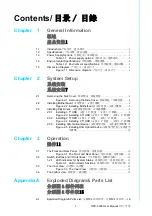
Summary of Contents for HPC-5000

Page 1: ...User Manual HPC 5000 Small Tower Server Chassis for ATX Mini ITX Motherboard ATX Mini ITX ATX Mini ITX...

Page 2: ...d in any form or by any means without the prior written permission of Advantech Co Ltd Information provided in this manual is intended to be accurate and reliable How ever Advantech Co Ltd assumes no...

Page 3: ...F it may damage the equipment 9 The openings on the enclosure are for air convection Protect the equipment from overheating DO NOT COVER THE OPENINGS 10 Make sure the voltage of the power source is co...

Page 4: ...e and 2 this device must accept any interference received including interference that may cause undesired operation 20 CAUTION Always completely disconnect the power cord from your chassis whenever yo...

Page 5: ...v HPC 5000 User Manual 15 16 17 18 CD IEC 60825 19 FCC 15 1 2 20 21 22 1 2 3 4 5 6 7 8 0 C 32 F 40 C 104 F 9 10 11 12 13 14 15 16 CLASS I LASER PRODUCT KLASS I LASER PRODUKT...

Page 6: ...trial environments Whether your new Advantech equipment is destined for the labo ratory or the factory floor you can be assured that your product will provide the reliability and ease of operation fo...

Page 7: ...pplication requirements or spe cific information on the installation and operation of any of our products Product Warranty Advantech warrants to you the original purchaser that each of its products wi...

Page 8: ...as defective obtain an RMA return merchandise authorization number from your dealer This allows us to process your return more quickly 4 Carefully pack the defective product a fully completed Repair a...

Page 9: ...ely We have carefully inspected the product mechanically and electrically before shipment It should be free of marks and scratches and in perfect working order upon receipt As you unpack the product c...

Page 10: ...HPC 5000 User Manual x...

Page 11: ...rboard 9 2 3 Installing Disk Drives 9 2 3 1 Installing 3 5 HDD 3 5 3 5 9 Figure 2 3 Installing 3 5 HDD 3 5 3 5 9 2 3 2 Installing 2 5 HDD 2 5 2 5 10 Figure 2 4 Installing 2 5 HDD 2 5 2 5 1 0 2 3 3 Ins...

Page 12: ...xploded Diagrams Parts List 16 Table A 1 Parts list 17 Appendix B Power board cable instruction 19 B 1 Top view of power distribution board 20 B 2 Connector pin assignment 21 Table B 1 CN1 21 Table B...

Page 13: ...Chapter 1 1 General Information...

Page 14: ...ending on the high or low temperatures inside the chassis A wide range of standard computing peripherals can be integrated with these chassis to accommodate robust applications in rugged environments...

Page 15: ...12 cm x 12 cm 82 CFM PWM 1 8cm 10 W x H x D 192 x 376 7 x 338 5 7 56 x 14 83 x 13 33 1 3 Power Supply Options Table 1 1 Power supply options Watt 300W 500W Input rating 100 127 Vac 200 240 Vac 100 24...

Page 16: ...ronment specifications Environment Operating Non operating Temperature 0 40 C 32 104 F 40 70 C 40 158 F Humidity 10 95 40 C non condensing 10 95 60 C non condensing Vibration 5 500Hz 1G rms 2 G Shock...

Page 17: ...5 HPC 5000 User Manual Chapter 1 General Information 1 5 Dimension Diagram Figure 1 1 Dimension diagram...

Page 18: ...HPC 5000 User Manual 6...

Page 19: ...Chapter 2 2 System Setup...

Page 20: ...Removing the Side Cover Note Use caution when installing or operating the components with the chas sis open Be sure to turn off the power unplug the power cord and ground yourself by touching the meta...

Page 21: ...HPC 5000 User Manual Chapter 2 System Setup 2 2 Installing Motherboard Figure 2 2 Installing Motherboard 2 3 Installing Disk Drives 2 3 1 Installing 3 5 HDD 3 5 3 5 Figure 2 3 Installing 3 5 HDD 3 5 3...

Page 22: ...ure 2 4 Installing 2 5 HDD 2 5 2 5 When the length of expansion card is longer than 8 5 21 6cm we suggest to use a 2 5 HDD bracket in the second HDD space 8 5 21 6 2 5 8 5 21 6 2 5 2 3 3 Installing Sl...

Page 23: ...Chapter 3 3 Operation...

Page 24: ...sys tem ATX power ATX ATX USB 2 0 3 0 ports For connecting a wide range of USB devices for data transfer backup or input USB 2 0 3 0 USB USB 2 0 3 0 USB 3 2 1 LED indicators for System Status 2x USB...

Page 25: ...o ATX Mini ITX motherboard Micro ATX Mini ITX 12cm system fan 300 500W Single PSU 300 500W PSU 300 500W PSU Keylock bracket Keylock 8cm system fan optional 8cm 8cm 2 5 3 5 HDD space 2 5 3 5 HDD 2 5 3...

Page 26: ...HPC 5000 User Manual 14...

Page 27: ...Appendix A A Exploded Diagram Parts List...

Page 28: ...HPC 5000 User Manual 16 A 1 Exploded Diagram Parts List Figure A 1 Exploded Diagrams Parts List...

Page 29: ...chassis 9 Air filter bracket 2 Power supply unit 10 HDD bracket 3 Side cover 11 Slim ODD bracket 4 Chassis feet 12 Front USB port cable USB USB 5 Air filter cover 13 Front USB port cable bracket USB U...

Page 30: ...HPC 5000 User Manual 18...

Page 31: ...Appendix B B Power board cable instruction...

Page 32: ...or 8pin 12V connector of PCIe slot PCIe 4 8 12V PCIe 4 8 12V 1700025828 01 1 Default in accessory box CN2 8P connector to 6 2 connector for GPU card power 8P 6 2 GPU 8P 6 2 GPU 1700025829 01 1 Option...

Page 33: ...GND 2 Black GND 3 Black GND 4 Black GND 5 Yellow 12VDC 6 Yellow 12VDC 7 Yellow 12VDC 8 Yellow 12VDC Table B 2 CN2 3 4 5 6 7 Pin number Color Signal 1 Yellow 12VDC 2 Yellow 12VDC 3 Yellow 12VDC 4 Black...

Page 34: ...No part of this publication may be reproduced in any form or by any means electronic photocopying recording or otherwise without prior written permis sion of the publisher All brand and product names...

Reviews: