background image

HPC-5000 User Manual / 

用户手册

vi



設備內部有液體流入;



設備曾暴露在過於潮濕的環境中使用;



設備無法正常工作,或您無法透過用戶手冊來使其正常工作;



設備跌落或者損壞;



設備有明顯的外觀破損。

17.

注意:電腦配置了由電池供電的即時時鐘電路,如果更換錯誤的電池,將有爆 
炸的危險。因此,只可以使用製造商推薦的同一種或者同等型號的電池進行替 
換。請按照製造商的指示處理舊電池。

18.

電腦提供的光碟機,已符合適當的安全標準,包括 IEC 60825。

19.

設備符合 FCC 規則第 15 款的規定。操作受如下兩個條件限制:
(1) 本設備不得產生有害的干擾,而且 
(2) 本設備必須能經受干擾,包括可能引起意外操作的干擾。

20.

注意:無論何時進行操作,請務必完全關閉機箱電源。不可在電源接通時進行設 
備連接,以避免瞬間電流損壞敏感電子元件。只有專業技術人員才可以打開機 
箱。

21.

注意:接觸產品的主板、背板或擴充卡前,請先確保您接地來移除身上附帶的靜 
電。由於現在的電子設備對靜電十分敏感,為了安全起見,請使用接地腕環。請 
將所有電子元件放在無靜電的表面或靜電屏蔽袋中。

22.

注意:未經專業認可的元件會損壞設備。請使用附件盒中提供的元件 (如螺絲) 
以確保正確的安裝。

A Message to the Customer

/ 致客戶的訊息


Advantech Customer Services

/ 研华为客户提供的服务 / 研華為客戶提供的服務

Each and every Advantech product is built to the most exacting specifications to
ensure reliable performance in the harsh and demanding conditions typical of indus-
trial environments. Whether your new Advantech equipment is destined for the labo-
ratory or the factory floor, you can be assured that your product will provide the
reliability and ease of operation for which the name Advantech has come to be
known. Your satisfaction is our primary concern. Here is a guide to Advantech’s cus-
tomer services. 
To ensure you get the full benefit of our services, please follow the instructions below
carefully.

研华的每一款产品都是严格按照规格生产的。因此,产品的可靠性在恶劣粗糙的工业
环境下也可以得到保证。无论您购买的研华产品置于实验室还是工厂,皆可确保研华
产品之可靠性和易于操作性。客户的满意是我们最关注的。下面是研华客户服务指南。
为保证您从我们的服务中获得最大的利益,请谨慎遵循下面的操作指南。

研華的每一款產品都是嚴格按照規格生產的。因此,產品的可靠性在惡劣粗糙的工業
環境下也可以得到保證。無論您購買的研華產品置於實驗室還是工廠,皆可確保研華
產品之可靠性和易於操作性。客戶的滿意是我們最關注的。以下是研華客戶服務指南。
為保證您從我們的服務中獲得最大的利益,請謹慎遵循下面的操作指南。

CLASS I LASER PRODUCT

KLASS I LASER PRODUKT

Summary of Contents for HPC-5000

Page 1: ...User Manual HPC 5000 Small Tower Server Chassis for ATX Mini ITX Motherboard ATX Mini ITX ATX Mini ITX...

Page 2: ...d in any form or by any means without the prior written permission of Advantech Co Ltd Information provided in this manual is intended to be accurate and reliable How ever Advantech Co Ltd assumes no...

Page 3: ...F it may damage the equipment 9 The openings on the enclosure are for air convection Protect the equipment from overheating DO NOT COVER THE OPENINGS 10 Make sure the voltage of the power source is co...

Page 4: ...e and 2 this device must accept any interference received including interference that may cause undesired operation 20 CAUTION Always completely disconnect the power cord from your chassis whenever yo...

Page 5: ...v HPC 5000 User Manual 15 16 17 18 CD IEC 60825 19 FCC 15 1 2 20 21 22 1 2 3 4 5 6 7 8 0 C 32 F 40 C 104 F 9 10 11 12 13 14 15 16 CLASS I LASER PRODUCT KLASS I LASER PRODUKT...

Page 6: ...trial environments Whether your new Advantech equipment is destined for the labo ratory or the factory floor you can be assured that your product will provide the reliability and ease of operation fo...

Page 7: ...pplication requirements or spe cific information on the installation and operation of any of our products Product Warranty Advantech warrants to you the original purchaser that each of its products wi...

Page 8: ...as defective obtain an RMA return merchandise authorization number from your dealer This allows us to process your return more quickly 4 Carefully pack the defective product a fully completed Repair a...

Page 9: ...ely We have carefully inspected the product mechanically and electrically before shipment It should be free of marks and scratches and in perfect working order upon receipt As you unpack the product c...

Page 10: ...HPC 5000 User Manual x...

Page 11: ...rboard 9 2 3 Installing Disk Drives 9 2 3 1 Installing 3 5 HDD 3 5 3 5 9 Figure 2 3 Installing 3 5 HDD 3 5 3 5 9 2 3 2 Installing 2 5 HDD 2 5 2 5 10 Figure 2 4 Installing 2 5 HDD 2 5 2 5 1 0 2 3 3 Ins...

Page 12: ...xploded Diagrams Parts List 16 Table A 1 Parts list 17 Appendix B Power board cable instruction 19 B 1 Top view of power distribution board 20 B 2 Connector pin assignment 21 Table B 1 CN1 21 Table B...

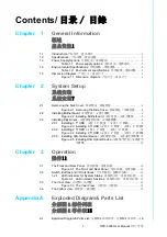
Page 13: ...Chapter 1 1 General Information...

Page 14: ...ending on the high or low temperatures inside the chassis A wide range of standard computing peripherals can be integrated with these chassis to accommodate robust applications in rugged environments...

Page 15: ...12 cm x 12 cm 82 CFM PWM 1 8cm 10 W x H x D 192 x 376 7 x 338 5 7 56 x 14 83 x 13 33 1 3 Power Supply Options Table 1 1 Power supply options Watt 300W 500W Input rating 100 127 Vac 200 240 Vac 100 24...

Page 16: ...ronment specifications Environment Operating Non operating Temperature 0 40 C 32 104 F 40 70 C 40 158 F Humidity 10 95 40 C non condensing 10 95 60 C non condensing Vibration 5 500Hz 1G rms 2 G Shock...

Page 17: ...5 HPC 5000 User Manual Chapter 1 General Information 1 5 Dimension Diagram Figure 1 1 Dimension diagram...

Page 18: ...HPC 5000 User Manual 6...

Page 19: ...Chapter 2 2 System Setup...

Page 20: ...Removing the Side Cover Note Use caution when installing or operating the components with the chas sis open Be sure to turn off the power unplug the power cord and ground yourself by touching the meta...

Page 21: ...HPC 5000 User Manual Chapter 2 System Setup 2 2 Installing Motherboard Figure 2 2 Installing Motherboard 2 3 Installing Disk Drives 2 3 1 Installing 3 5 HDD 3 5 3 5 Figure 2 3 Installing 3 5 HDD 3 5 3...

Page 22: ...ure 2 4 Installing 2 5 HDD 2 5 2 5 When the length of expansion card is longer than 8 5 21 6cm we suggest to use a 2 5 HDD bracket in the second HDD space 8 5 21 6 2 5 8 5 21 6 2 5 2 3 3 Installing Sl...

Page 23: ...Chapter 3 3 Operation...

Page 24: ...sys tem ATX power ATX ATX USB 2 0 3 0 ports For connecting a wide range of USB devices for data transfer backup or input USB 2 0 3 0 USB USB 2 0 3 0 USB 3 2 1 LED indicators for System Status 2x USB...

Page 25: ...o ATX Mini ITX motherboard Micro ATX Mini ITX 12cm system fan 300 500W Single PSU 300 500W PSU 300 500W PSU Keylock bracket Keylock 8cm system fan optional 8cm 8cm 2 5 3 5 HDD space 2 5 3 5 HDD 2 5 3...

Page 26: ...HPC 5000 User Manual 14...

Page 27: ...Appendix A A Exploded Diagram Parts List...

Page 28: ...HPC 5000 User Manual 16 A 1 Exploded Diagram Parts List Figure A 1 Exploded Diagrams Parts List...

Page 29: ...chassis 9 Air filter bracket 2 Power supply unit 10 HDD bracket 3 Side cover 11 Slim ODD bracket 4 Chassis feet 12 Front USB port cable USB USB 5 Air filter cover 13 Front USB port cable bracket USB U...

Page 30: ...HPC 5000 User Manual 18...

Page 31: ...Appendix B B Power board cable instruction...

Page 32: ...or 8pin 12V connector of PCIe slot PCIe 4 8 12V PCIe 4 8 12V 1700025828 01 1 Default in accessory box CN2 8P connector to 6 2 connector for GPU card power 8P 6 2 GPU 8P 6 2 GPU 1700025829 01 1 Option...

Page 33: ...GND 2 Black GND 3 Black GND 4 Black GND 5 Yellow 12VDC 6 Yellow 12VDC 7 Yellow 12VDC 8 Yellow 12VDC Table B 2 CN2 3 4 5 6 7 Pin number Color Signal 1 Yellow 12VDC 2 Yellow 12VDC 3 Yellow 12VDC 4 Black...

Page 34: ...No part of this publication may be reproduced in any form or by any means electronic photocopying recording or otherwise without prior written permis sion of the publisher All brand and product names...

Reviews: