

HPC-7120 User Manual
/ 用户手册
16
3.1
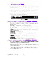
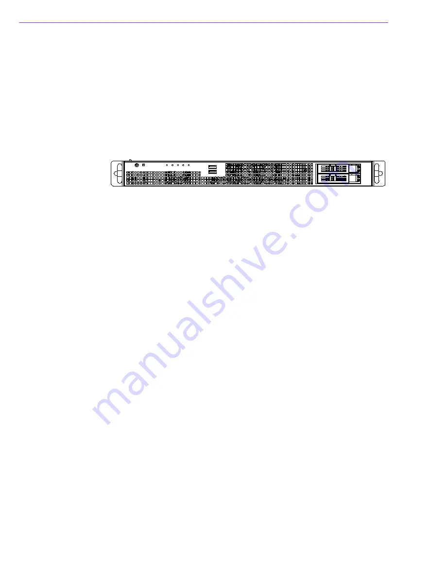
The Front Panel
/ 前面板
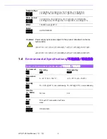
The front panel features five LED indicators, a power switch, a system reset button,
dual USB3.0 ports and two hot swappable 2.5" HDD trays. Specific functions are
described as below.
前面板有 4 个 LED 指示灯、1 个电源开关、1 个系统重启按钮、双 USB3.0 接口和 2 个
可移动式磁盘托架。其具体功能将在后面进行介绍。
前面板有
5
個 LED 指示燈、1 個電源開關、1 個系統重啟按鈕、雙 USB3.0 介面和兩個
可移動式硬碟托架。其具體功能將在後面進行介紹。
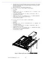
Figure 3.1
前視圖
3.1.1
Switch, Buttons and I/O Interfaces
/ 开关和按钮 / 開關和按鈕
Momentary Power switch:
Press this switch to turn the system power on or off.
Please use system shutdown or press this switch for few seconds to turn off the sys-
tem ATX power.
System Reset button:
Press this button to reboot the system.
Dual USB3.0 ports:
For connecting a wide range of USB3.0 devices for data trans-
fer, backup or input.
电源开关:按下此按钮可开启或关闭系统电源。请使用系统关机或持续按下此按钮数
秒钟以关闭系统 ATX 电源。
系统重启按钮:按下此按钮可重启系统。
双 USB3.0 接口:此接口可连接各种 USB3.0 设备用于数据传输、备份或输入。
電源開關:按下此按鈕可開啟或關閉系統電源。請使用系統關機或持續按下此按鈕數
秒鐘以關閉系統 ATX 電源。
系統重啟按鈕:按下此按鈕可重啟系統。
雙 USB3.0 接頭:此接頭可連接各種 USB3.0 設備用於資料傳輸、備份或輸入。
3.1.2
LED indicators for System Status
/ 系统指示灯 / 系統指示燈
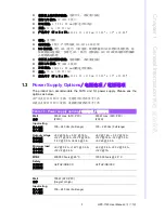
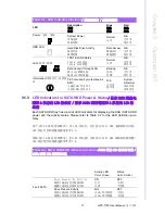
Five LEDs are placed on the top of the front panel to indicate system power and
activity. Refer to Table 3.1 for the LED definition summary.
机箱前面板上方配有 5 个 LED 指示灯,能够显示系统是否正常运行及运行状态。LED 指
示灯的功能描述请参考表 3.1。
主機殼前面板上方配有 5 個 LED 指示燈,能夠顯示系統是否正常運行及運行狀態。LED
指示燈的功能描述請參考表 3.1。
Summary of Contents for HPC-7120
Page 9: ...ix HPC 7120 User Manual...
Page 10: ...HPC 7120 User Manual x...
Page 13: ...Chapter 1 1 General Information...
Page 18: ...HPC 7120 User Manual 6...
Page 19: ...Chapter 2 2 System Setup...
Page 26: ...HPC 7120 User Manual 14...
Page 27: ...Chapter 3 3 Operation...
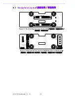
Page 33: ...Chapter 4 4 Dual Slot SATA Backplane SATA SATA...
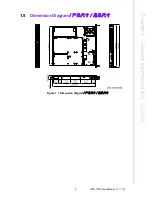
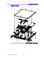
Page 35: ...Appendix A A Exploded Diagram Parts List...
Page 36: ...HPC 7120 User Manual 24 A 1 Exploded Diagram Parts List Figure A 1 Exploded Diagram Parts List...
Page 37: ...25 HPC 7120 User Manual Appendix A Exploded Diagram Parts List...


