


HPC-7400 User Manual
/ 用户手册
2
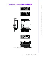
1.1
Introduction/
产品简介 / 產品簡介
The HPC-7400 series is a 4U short-depth rackmount / tower chassis designed for
digital surveillance, video, AOI, workstation or telecom applications which have
higher storage demand in space-sensitive environment. With the latest industrial
design, the HPC-7400 represents a breakthrough from the traditional, rigid concept
of industrial PCs, and provides users with both a high-performance and a state-of-
the-art operating platform. This series supports versatile EATX/ATX motherboards,
with a highly efficient switching power supply and easy-to-maintain cooling fans. The
series provides two 5.25" (convertible to eight 2.5” or three 3.5”) drive bays and four
(after adding "storage upgrade kit") bays for internal storage usage, which provide
flexibility to empower customer product solutions. The intelligent LED indicators show
system status such as Power, HDD and LAN, to minimize system downtime. Mean-
while, system fan's rotation speed increases or decreases depending on high or low
temperature inside the chassis, to minimize system noise while light system loading.
A wide range of standard computing peripherals can be integrated with these chassis
to accommodate robust applications in rugged environments, 24 hours a day, 7 days
a week.
HPC-7400 系列 4U 上架式及直立式两用服务器级工业机箱,专为有大量储存需求的数位
监视系统、影像处理、自动化检测设备、工作站或网络通讯等等应用而设计,适用于
使用者环境有空间限制的需求。HPC-7400 打破了工业电脑传统的刻板形象,采用最新
的工业外观设计,为用户提供了高性能、最尖端的操作平台。该系列支持 EATX/ATX 母
板,高效切换电源和易维护风扇。HPC-7400 提供了 2 个 5.25
"
(用于光碟机或可转换
为 8 个 2.5
"
或 3 个 3.5
"
)HDD 抽取盒和最多 4 个 (当安装磁碟升级套组后)內置硬盘
托架,能够为资料存储提供灵活的解决方案。智慧型 LED 警示灯可监控系统状态如电
源、HDD 和网络,从而最大限度降低了系统瘫痪,另外系统风扇还能依据机箱内温度的
高低而增减转速以便在低系统负载时有效降低噪音。该系列机箱还可集成广泛的标准
电脑周边设备,从而满足了各种应用在苛刻环境下 7 天 24 小时无间断运行。
HPC-7400 系列 4U 上架式及直立式兩用伺服器級工業機箱,專為有大量儲存需求的數位
監視系統、影像處理、自動化檢測設備、工作站或網路通訊等等應用而設計,適用於
使用者環境有空間限制的需求。HPC-7400 打破了工業電腦傳統的刻板形象,採用最新
的工業外觀設計,為用戶提供了高性能、最尖端的操作平臺。該系列支援 EATX/ATX 母
板,高效切換電源和易維護風扇。HPC-7400 提供了 2 個 5.25
"
(用於光碟機或可轉換
為 8 個 2.5
"
或 3 個 3.5
"
)HDD 抽取盒和最多 4 個 (當安裝磁碟升級套組後)內置硬碟
托架,能夠為資料存儲提供靈活的解決方案。智慧型 LED 警示燈可監控系統狀態如電
源、HDD 和網路,從而最大限度降低了系統癱瘓,另外系統風扇還能依據機箱內溫度的
高低而增減轉速以便在低系統負載時有效降低噪音。該系列機箱還可整合廣泛的標準
電腦週邊設備,從而滿足了各種應用在苛刻環境下 7 天 24 小時無間斷運行。
1.2
Specifications
/ 产品规格 / 產品規格
Construction:
Heavy-duty steel
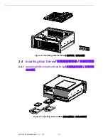
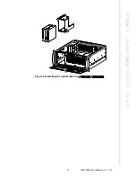
Disk Drive Capacity:
Two 5.25" disk drive bay (front), two 3.5" internal drive
bay (rear), and optional two 3.5" internal drive bay (inside)
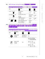
LED Indicators:
Single-color LEDs (blue) for Power, HDD activity and LAN sta-
tus.
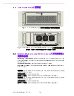
Switch and Buttons on Front Panel:
Power switch and system reset button
Front I/O Interfaces:
Dual USB ports (USB 3.0)
Security Protection:
The disk drive bay, power switch, system reset button and
USB ports are all behind the lockable door.
Summary of Contents for HPC-7400
Page 10: ...HPC 7400 User Manual x...
Page 13: ...Chapter 1 1 General Information...
Page 18: ...HPC 7400 User Manual 6...
Page 19: ...Chapter 2 2 System Setup...
Page 23: ...11 HPC 7400 User Manual Chapter 2 System Setup Figure 2 6 Installing the optical disk drive...
Page 26: ...HPC 7400 User Manual 14...
Page 27: ...Chapter 3 3 Operation...
Page 32: ...HPC 7742 User Manual 20...