


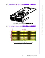
3
HPC-7400 User Manual
/ 用户手册
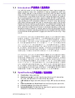
Chapter 1
G
eneral
Information
概述 產品資訊
Cooling System:
Three 8 cm x 8 cm (142 CFM) front-accessible PWM fans;
two optional 6cm rear fans
Air Filters:
One easily maintained reusable filters behind the front door
Weight:
(TBD)
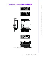
Dimensions (W x H x D):
482 x 177 x 448 mm (19" x 7.0" x 17.6")
构造:重型钢
磁盘容量:2个5.25
"
前窗HDD抽取盒, 2个后窗3.5
"
HDD抽取盒, 2个选购内置硬盘
托架
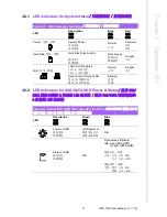
LED 指示灯:单色 LED (蓝色)用于电源、硬盘传输状态和 LAN 状态。
前面板上的开关和按钮:电源开关和系统复位按钮
前部 I/O 接口:双 USB 接口 (USB 3.0)
安全保护:存储抽取盒、电源开关、系统重启按钮、警报复位按钮、单键操作系
统恢复按钮和 USB 接口全部由带锁门保护
冷却系统:3 个 8 cm x 8 cm (142 CFM) 可前方更换冷却 PWM 风扇; 2 个选配 6cm
后方风扇
空气过滤器:1 个易于维护并且可重复使用的过滤器位于前门后部
重量:(TBD)
产品尺寸 (W x H x D):482 x 177 x 448 mm (19
"
x 7.0
"
x 17.6
"
)
構造:重型鋼
磁碟容量:2個5.25
"
前窗HDD抽取盒, 2個後窗3.5
"
HDD抽取盒, 2個選購內置硬碟
托架
LED 指示燈:單色 LED (藍色)用於電源、硬碟傳輸狀態和 LAN 狀態。
前面板上的開關和按鈕:電源開關和系統重啟按鈕
前部 I/O 接頭:雙 USB 接頭 (USB 3.0)
安全保護:儲存抽取盒、電源開關、系統重啟按鈕和 USB 接頭全部由帶鎖門保護
冷卻系統:3 個 8 cm x 8 cm (142 CFM) 可前方更換冷卻 PWM 風扇; 2 個選配 6cm
後方風扇
濾網:1 個易於維護並且可重複使用的濾網位於前門後部
重量:(TBD)
產品尺寸 (W x H x D):482 x 177 x 448 mm (19
"
x 7.0
"
x 17.6
"
)
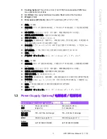
1.3
Power Supply Options
/ 电源选项 / 電源選項
Table 1.1: Power supply options
/ 电源选项 / 電源選項
Watt
功率
700 W (ATX, PFC)
(single 1U)
1400 W (ATX, PFC)
(1+1 redundant)
Input rating
输入电压
輸入電壓
100 ~ 240 Vac (Full range)
100 ~ 240 Vac (Full range)
MTBF
100,000 hours @ 25° C
100,000 hours @ 25° C
Safety
安规认证
安規認證
UL/TUV/CB/CCC/BSMI
UL/TUV/CB/CCC/BSMI
Summary of Contents for HPC-7400
Page 10: ...HPC 7400 User Manual x...
Page 13: ...Chapter 1 1 General Information...
Page 18: ...HPC 7400 User Manual 6...
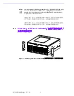
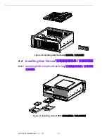
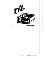
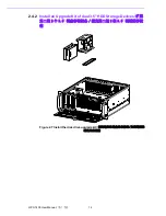
Page 19: ...Chapter 2 2 System Setup...
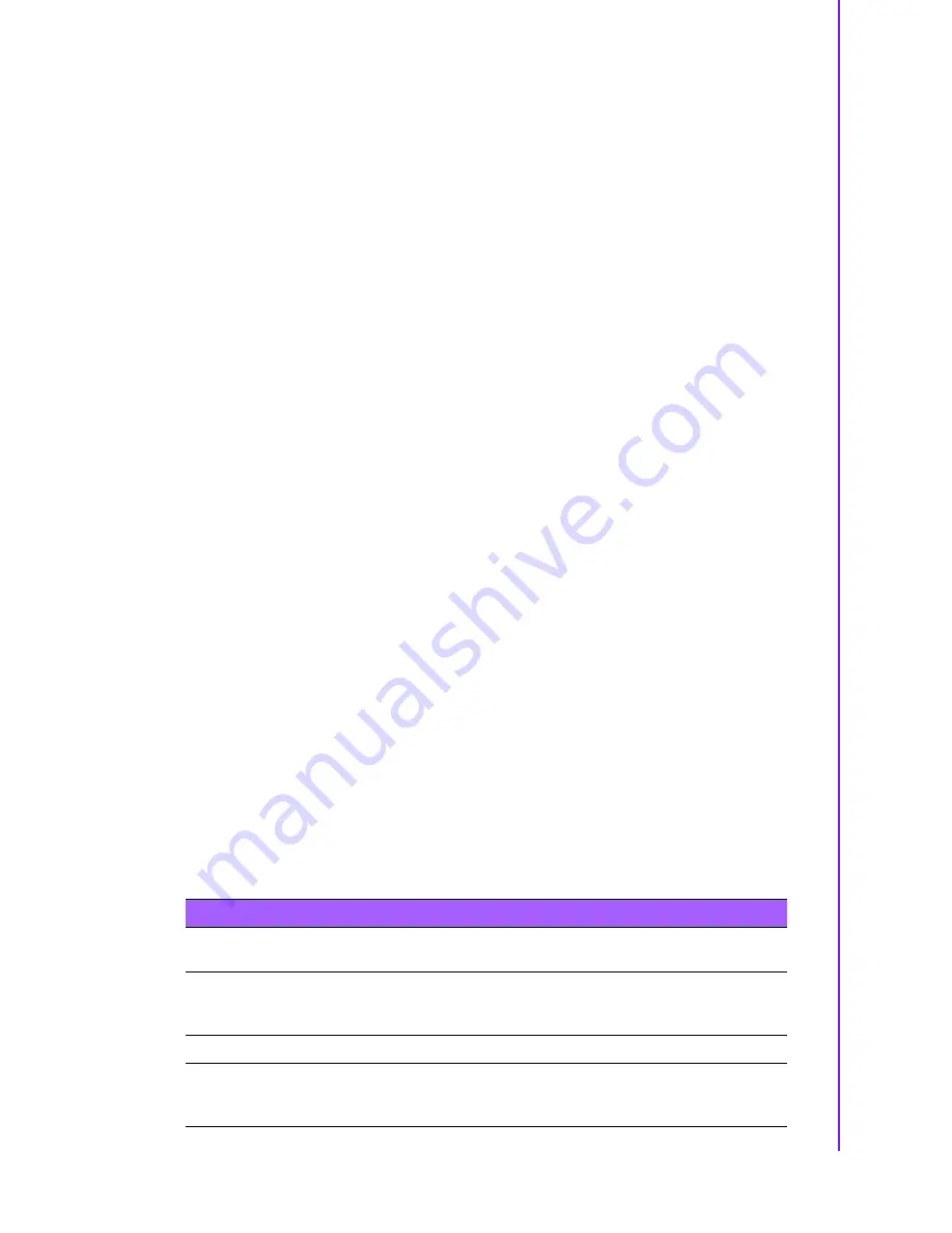
Page 23: ...11 HPC 7400 User Manual Chapter 2 System Setup Figure 2 6 Installing the optical disk drive...
Page 26: ...HPC 7400 User Manual 14...
Page 27: ...Chapter 3 3 Operation...
Page 32: ...HPC 7742 User Manual 20...