
23
HPC-7400 User Manual
/ 用户手册
Appendix A
E
xploded
Diagram&
Parts
L
ist
分解图
&
部件列表
分解圖
&
零件
表
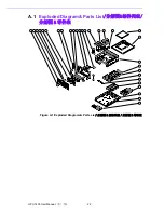
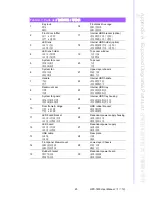
Table A.1: Parts list
/ 部件列表 / 零件表
1
Key lock
锁头
鎖頭
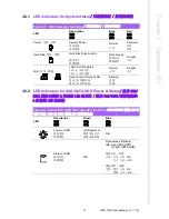
16
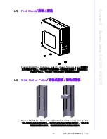
Front disk drive cage
抽取盒框架
抽取盒框架
2
Front door & filter
前门 & 滤网
前門 & 濾網
17
Internal HDD bracket (option)
内装硬盘支架 ( 选配 )
內裝硬碟支架 ( 選配 )
3
LED lens
LED 导光柱
LED 導光柱
18
Internal HDD holder (option)
内装硬盘固定架 ( 选配 )
內裝硬碟固定架 ( 選配 )
4
LED lens holder
LED 导光柱罩
LED 導光柱罩
19
Top cover window
上盖开窗
上蓋開窗
5
System fan cover
系统风扇盖
系統風扇蓋
20
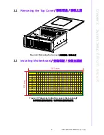
Top cover
上盖
上蓋
6
System fan
系统风扇
系統風扇
21
Upper-layer chassis
机箱上層
機箱上层
7
Handle
手柄
把手
22
Internal HDD handle
内装硬盘手柄
內裝硬碟把手
8
Rackmount ear
耳翼
耳翼
23
Internal HDD tray
内装硬盘抽取盒
內裝硬碟抽取盒
9
System fan guard
系统风扇保护罩
系統風扇保護罩
24
Internal HDD tray housing
内装硬盘抽取盒支架
內裝硬碟抽取盒支架
10
Door frame & Hinge
门框 & 铰链
門框 & 鉸鍊
25
HDD rubber bracket
硬盘缓冲垫
內裝緩衝墊
11
LED board bracket
LED 指示灯板支架
LED 指示燈板支架
26
Redundant power supply housing
备援电源支架
備援電源支架
12
LED board
LED 指示灯板
LED 指示燈板
27
Redundant power supply
备援电源
備援電源
13
USB cable
USB 线
USB 線
28
Rear plate
后板
後板
14
Front panel drawer cover
抽取盒前盖板
抽取盒前蓋板
29
Lower-layer Chassis
机箱下層
機箱下层
15
Rubber bracket
缓冲垫支架
緩衝墊支架
30
Redundant power board
备援电源板
備援電源板
Summary of Contents for HPC-7400
Page 10: ...HPC 7400 User Manual x...
Page 13: ...Chapter 1 1 General Information...
Page 18: ...HPC 7400 User Manual 6...
Page 19: ...Chapter 2 2 System Setup...
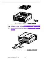
Page 23: ...11 HPC 7400 User Manual Chapter 2 System Setup Figure 2 6 Installing the optical disk drive...
Page 26: ...HPC 7400 User Manual 14...
Page 27: ...Chapter 3 3 Operation...
Page 32: ...HPC 7742 User Manual 20...


