HPC-7480 User Manual
14
3.1
The Front Panel
The front panel features a lockable door. The user can close the door with or without
the key using the user-friendly rotary lock. Upon opening the door, one sees eight
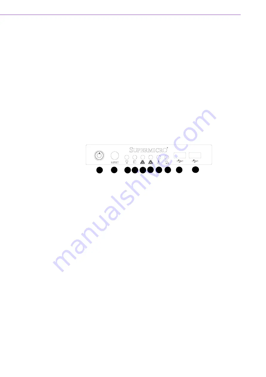
3.5" SAS/SATA hot-swap hard drive trays. There is a momentary power switch, two
reserved system reset buttons, dual USB ports, and six LED indicators. Their individ-
ual functions are described as below.
3.1.1
Switch, Button and I/O Interfaces
Momentary Power switch:
Press this switch to turn the system power on or off.
Please use system shutdown or press this switch for few seconds to turn off the
system ATX power.
System Reset button:
Press this button to reboot the system.
Dual USB ports:
For connecting a wide range of USB devices for data transfer,
backup or input.
3.1.2
LED Indicators for System Status
The following diagram defines each component of the front LED panel.
Figure 3.1 Front control panel
1.
Power Button
2.
System Reset
3.
Power Indicator
4.
HDD Activity Indicator
5.
LAN1 Indicator
6.
LAN2 Indicator
7.
CPU Temperature/Fan Failure Indicator
8.
Power Failure Indicator
9.
USB Port
10.
USB Port
1
2
3
4
5
6
10
9
8
7
Summary of Contents for HPC-7480
Page 6: ...HPC 7480 User Manual vi...
Page 9: ...Chapter 1 1 General Information...
Page 12: ...HPC 7480 User Manual 4...
Page 13: ...Chapter 2 2 System Setup...
Page 21: ...Chapter 3 3 Operation...
Page 25: ...Chapter 4 4 SATA SAS Backplane...
Page 39: ...Appendix A A Chassis Screws...
Page 41: ...33 HPC 7480 User Manual Appendix A Chassis Screws...


