27
HPC-7480 User Manual
Chapter 4
S
ATA/SAS
Backplane
4.2.6.3
3. Activity LED Connector
The activity LED connector, designated JP26, is used to indicate the activity status of
each SATA drive. The activity LED connector is located on the front panel. For the
activity LED header to work properly, connect using a 10-pin LED cable.
4.2.6.4
4 ~ 11. SATA Ports
The SATA ports are used to connect the SATA drive cables. The 8 SATA ports are
designated #0 - #7.
4.2.6.5
12. Buzzer Reset
The buzzer reset jumper allows the buzzer to be reset when an alarm has occured.
4.2.7
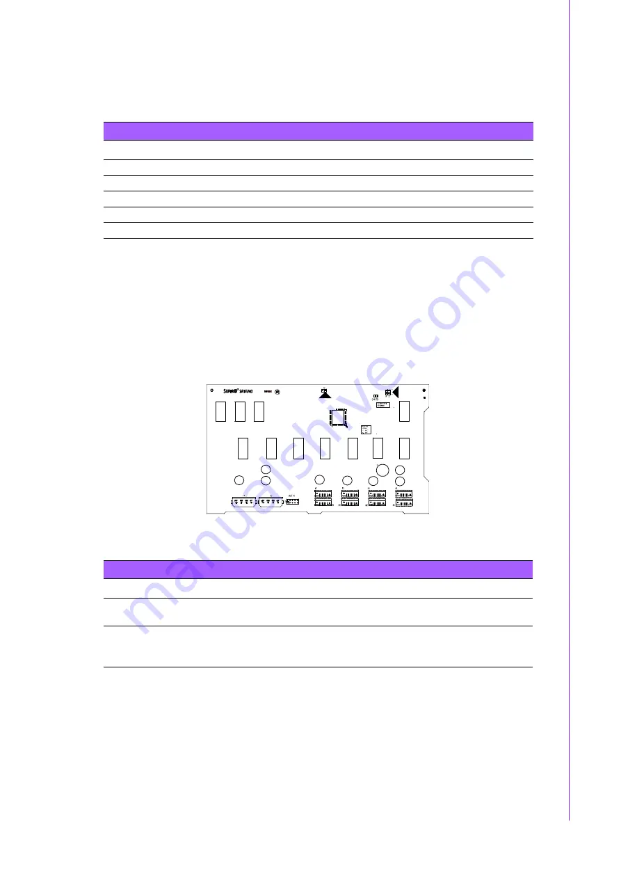
Front Jumper Locations and Pin Definitions
Figure 4.6 Front Jumpers
Table 4.13: SATA Activity LED Header Pin Definitions
Pin #
Definition
Pin #
Definition
1
ACT IN#0
6
ACT IN#4
2
ACT IN#1
7
ACT IN#5
3
ACT IN#2
8
ACT IN#6
4
ACT IN#3
9
ACT IN#7
5 Ground
10 Empty
Table 4.14: Socket Settings
Jumper
Setting
Note
JP18
Open: No Reset (Default)
Closed: Reset
Buzzer reset*
JP25
Open: 45°C
1-2: 50°C (Default)
2-3: 55°C
Overheat temperature setting.
JP18
JP25
Summary of Contents for HPC-7480
Page 6: ...HPC 7480 User Manual vi...
Page 9: ...Chapter 1 1 General Information...
Page 12: ...HPC 7480 User Manual 4...
Page 13: ...Chapter 2 2 System Setup...
Page 21: ...Chapter 3 3 Operation...
Page 25: ...Chapter 4 4 SATA SAS Backplane...
Page 39: ...Appendix A A Chassis Screws...
Page 41: ...33 HPC 7480 User Manual Appendix A Chassis Screws...


