iDAQ-817_821 User Manual
8
There is only one ADC in the device. An analog multiplexer selects one of the analog
input channels at a time to be measured by the ADC. Therefore, the sample rate of
the ADC is shared by all enabled channels. Refer to Appendix A Specifications for
the sample rate supported. The ADC is of successive approximation register (SAR)
type.
A low-pass filter is placed in front of the ADC. This filter removes high frequency
noise in the input signal before entering the ADC, which can increase signal-to-noise
ratio (SNR) performance. It also avoids alias generation due to ADC conversion.
The device is equipped with a galvanic isolator, which can withstand a large continu
-
ous voltage between external side and internal side. This prevents internal circuit
from damaging when such fault condition happens.
2.3.2
Analog Output Connection
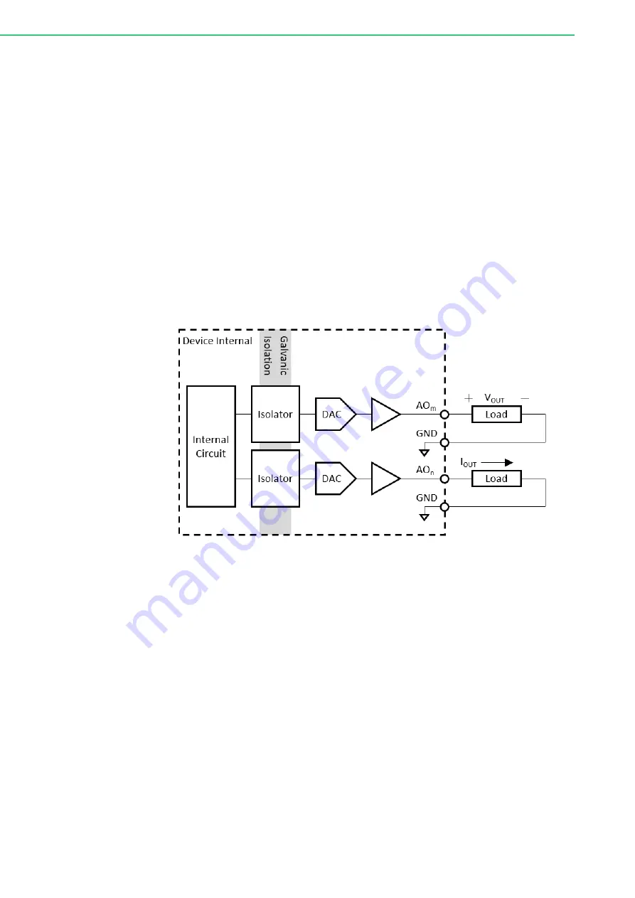
For an analog output channel to work, a digital form of data is sent to the digital-to-
analog converter (DAC) through a galvanic isolator. The DAC then outputs the corre
-
sponding voltage or current to the external load. Figure 2.4 shows the analog output
signal connection.
Figure 2.4 Analog output signal connection.
The analog output channels are of single-ended type, hence the negative terminal of
the external loads should be connected to GND pin.
Each channel can be configured independently by software to output multiple ranges
of voltage or current. User should ensure the load value is within the range as speci
-
fied in Appendix A Specifications, otherwise the output voltage or current may not
reach the specified value due to limitation of output driving capability.
The device is equipped with a galvanic isolator, which can withstand a large continu
-
ous voltage between external side and internal side. This prevents internal circuit
from damaging when such fault condition happens.
Summary of Contents for iDAQ-817
Page 1: ...User Manual iDAQ 817 iDAQ 821 Analog Input and output Industrial DAQ Modules ...
Page 8: ...iDAQ 817_821 User Manual viii ...
Page 11: ...Chapter 1 1 Start Using iDAQ 817 821 ...
Page 15: ...Chapter 2 2 Installation Guide ...
Page 20: ...iDAQ 817_821 User Manual 10 ...
Page 21: ...Chapter 3 3 Function Details ...
Page 29: ...Appendix A A Specifications ...
Page 33: ...Appendix B B System Dimensions ...
Page 35: ...25 iDAQ 817_821 User Manual Appendix B System Dimensions ...


